5
Installing Camera Using ATM Bracket
4.
Cut the zip tie strain relief being careful not to cut
the power or video wire. Damaged cables are not
covered under this product’s warranty.
HINT: Slide the zip tie off the plastic arm before
cutting the zip tie.
5.
Attach the camera bracket to the camera using the
screws and gaskets from step 1. Orient the camera
as needed. The Pixim logo on the camera should
point towards the floor, or the image will be upside
down on screen.
6.
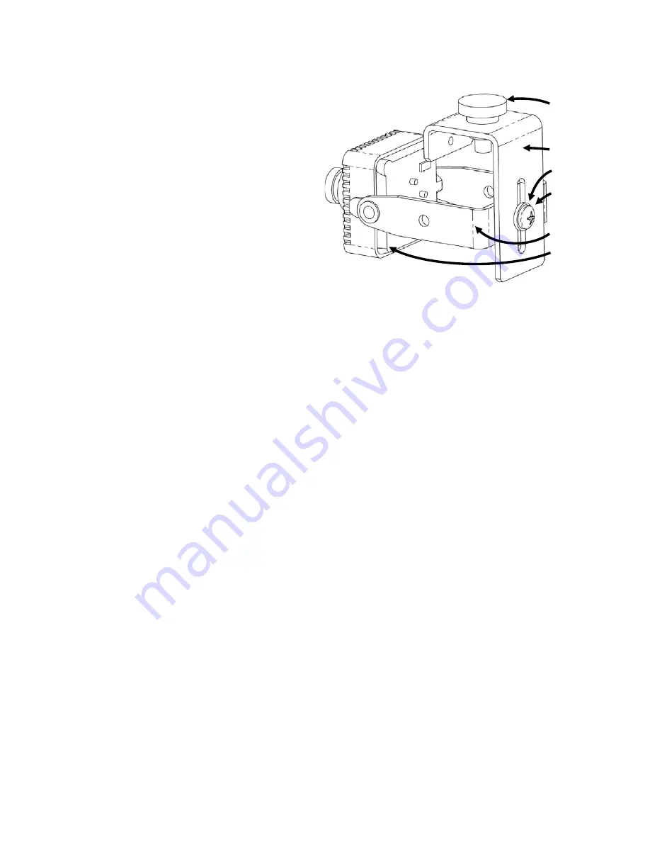
Attach the camera bracket to the ATM bracket (see
Figure 3) using the #10 washer and #10-32 screw
from the hardware kit. Adjust the camera bracket
up/down as needed before tightening the screw.
7.
Drill a mounting hole in the mounting surface that
will accept a ¼” fastener.
8.
Position the bracket under the mounting hole and
attach the camera assembly to the mounting
surface using the thumb screw.
9.
Position the camera as needed, then securely
tighten all fasteners.
10.
Provide strain relief to the camera cable using the
zip tie from the hardware kit.
11.
Supply power to the camera.
12.
Use a test monitor to ensure the camera is in focus
and pointing in the desired direction.
13.
If the camera is out of focus, loosen the nut
surrounding the lens, twist the lens right or left until
the image is in focus, then tighten the nut to secure
the lens in place.
Camera Configuration
The camera’s on-screen display (OSD) controls are
located on the back of the camera (see Figure 1).
Use the controls to navigate the OSD menu. Features
and options are shown in Appendix A. OSD controls
include Up, Down, Left, Right, and Select (center
button).
Hold down Select to enter the menu.
Figure 3 - Completed Assembly Using ATM Bracket
Thumb screw
ATM Bracket
#10 Washer
#10-32 x 3/8”
Screw
Camera Bracket
Camera
Summary of Contents for ATMN58KTS
Page 1: ...ATM Camera ATMN58KTS CAM690ATM CAM690ATM 28...
Page 2: ......


