20
Rev. 0
the GUI to be adjusted to any screen size and to show only the information that is of interest for a given application
without overwhelming the user with the large feature-set of the LTC2949.
Any custom GUI layout may be set as the default (View
→
Set Default Layout), stored to a specific file (View
→
Save Layout...) or reloaded (View
→
Get Default Layout or
Load Layout...). The default layout will always be reloaded
on start-up. The GUI may be reset to the factory default
layout by View
→
Reset Default Layout.
OPERATION CONTROL
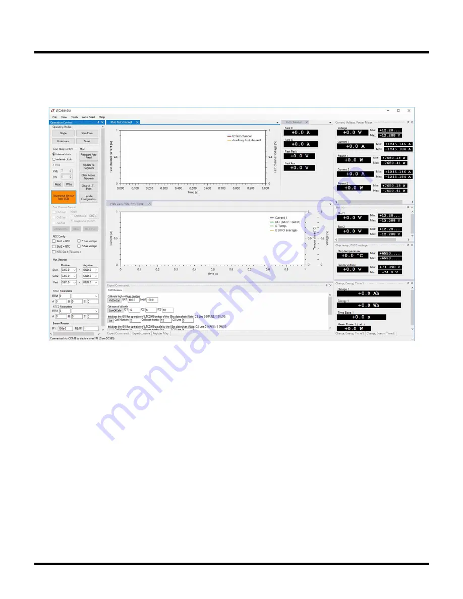
The Operation Control functions are:
1. Connect/Disconnect Device via USB (Linduino/
DC2026).
2. Enable/Disable Continuous measurement.
3. Make Slow Channel Single conversion.
4. Shutdown Device.
5. Reset Device.
Figure 19. GUI: Main Window
6. Time Base Control to set internal or external clock
frequency including calculation of PRE/DIV values for
a given clock (see also Tools Menu section).
7. Enable/Disable Register Auto Read. If enabled data
is automatically transferred from device to PC every
100ms (default), see Auto Read Menu section.
8. Manually Update All Registers (manually transfer all
data from device to PC).
9. Clear Accumulator and Tracking registers.
10. Clear Accumulator and Tracking registers and reset
all data in all plot windows.
11. Update Configuration from 2nd memory page
(ADJUPD which is necessary when changing gain
correction factors, ADC configuration etc.).
12. Configure ADCs (requires ADJUPD to become
effective).
LTC2949 WINDOWS GUI USAGE


