5
dc1755af
DEMO MANUAL DC1755A
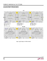
Figure 6. Typical Setup for a 6-Phase + 2-Phase Converter
RUN signals of the adjacent boards together. Next, locate
the exposed copper shapes on the four corners of the
board on the top and bottom layers. Use these shapes to
tie the VOUT, VIN and GND planes of the adjacent boards.
Next, select which phases will be the master or the slave.
Figure 6 shows the typical setup for a 6-phase + 2-phase
converter. Figure 7 shows the typical setup for a 12-phase
converter. For additional help and support, contact your
local LTC sales office.
BOARD #2
SIDE A = SLAVE
SIDE B = INDEPENDENT DUAL PHASE RAIL
R87, R88, R89, R91 = NOT STUFFED
R101, R102 = NOT STUFFED
R103 = NOT STUFFED
R104 = 0
Cu
GND
GND
TOP
BOTTOM
BOARD #1
BOARD #2
BOARD #2
BOARD #1
BOARD #1 = MASTER
R87, R88, R89, R91 = 0
R101, R102 = 0.0m
R103 = 0
R104 = NOT STUFFED
Cu
Cu
Cu
6 PHASE
CONVERTER
6 PHASE
CONVERTER
2 PHASE
CONVERTER
DC1755a F06
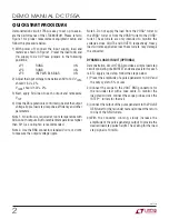
QUICK START PROCEDURE


