background image

Regulatory Notices and Fusing Information 

FCC 

This equipment has been tested and found to comply with the limits for a Class A digital device, 
pursuant to Part 15 of the FCC Rules. These limits are designed to provide reasonable protection 
against harmful interference when the equipment is operated in a commercial environment. This 
equipment generates, uses, and can radiate radio frequency energy and, if not installed and used in 
accordance with this instruction manual, may cause harmful interference to radio communications. 
Operation of this equipment in a residential area is likely to cause harmful interference in which case
the user will be required to correct the interference at his or her own expense. 

Canada

This Class A digital apparatus complies with Canadian ICES-003. 

UL

WARNING: Troubleshooting must be performed by a trained technician. Do not 
attempt to service this equipment unless you are qualified to do so. 

Check that the correct fuses have been installed. To reduce the risk of fire, replace 
only with fuses of the same type and rating. 

Exposed portions of the power supply assembly are electrically “hot”. In order to reduce the risk
of electrical shock, the power cord MUST be disconnected when the power supply assembly is 
removed. 

The ground terminal of the power plug is connected 
directly to the chassis of the unit. For continued protection 
against electric shock, a correctly wired and grounded 
(earthed) three-pin power outlet must be used. Do not use 
a ground-lifting adapter and never cut the ground pin on 
the three-prong plug. 

UK

As the colours of the cores in the mains lead may not correspond with the coloured markings 
identifying the terminals in your plug, proceed as follows: 

x

The core that is coloured green and yellow must be connected to the terminal in the 
plug identified by the letter E or by the earth symbol 

 or coloured green or green 

and yellow. 

x

The core that is coloured blue must be connected to the terminal that is marked with t
letter N or coloured black. 

x

The core that is coloured brown must be connected to the terminal that is marked with
the letter L or coloured red. 

x

This apparatus must be earthed. 

Summary of Contents for UPMAX

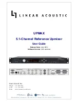
Page 1: ...UPMAX 5 1 Channel Reference Upmixer User Guide Release Date June 2013 Software Version 0 98 and later Linear Acoustic Inc Phone 717 735 3611 FAX 717 735 3612 Web www LinearAcoustic com...

Page 2: ...ING MATERIALS FAILURE TO RETURN UNIT IN ORIGINAL SHIPPING CARTON AND PACKING MATERIALS WILL RESULT IN A CHARGE FOR NEW SHIPPING MATERIALS LIMITATION OF PERIOD OF ACTION ON CONTRACT No action regardles...

Page 3: ...To reduce the risk of fire replace only with fuses of the same type and rating Exposed portions of the power supply assembly are electrically hot In order to reduce the risk of electrical shock the p...

Page 4: ...are eventuali rischi di scossa lettrica o d incendio vanno osservate le seguenti misure di sicurezza Assicurarsi che il selettore di cambio tensione sia posizionato sul valore corretto Assicurarsi che...

Page 5: ...connected to a power source 1 Open the fuse compartment door in the AC power input housing with a small flat blade screwdriver Figure 1 Carefully pull out the fuse carrier 2 Check that the replacement...

Page 6: ......

Page 7: ...ction 9 2 2 Installation 9 2 3 Rear Panel 10 2 3 1 Connection Ports 10 2 4 Quick Setup Notes 11 Chapter 3 Applications 13 3 1 Typical Scenarios 13 3 1 1 Two Channel Commercials and Interstitial Progra...

Page 8: ...2 Chapter 5 Troubleshooting 23 5 1 Problems and Possible Causes 23 5 1 1 Unit won t power on 23 5 1 2 Output Audio Clicks and Pops 23 5 1 3 Unit is Not Upmixing 24 5 1 4 Cannot Manually Control Upmixi...

Page 9: ...ar Acoustic UPMAX User Guide 3 List of Figures 1 1 Audio Block Diagram 6 2 1 Rear Panel 10 3 1 UPMAX in a commercial upmixing application 14 3 2 UPMAX with Dolby DP572 Dolby E Decoder 15 6 1 Electrica...

Page 10: ...Linear Acoustic UPMAX User Guide 4...

Page 11: ...passing of upmixing to enable discrete 5 1 channel audio to automatically pass untouched Built in independent LoRo LtRt encoder Relay bypassed digital inputs for mission critical broadcast application...

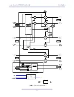
Page 12: ...epth Main Out Rs Main Out Ls Main Out LFE Main Out C Main Out Rf Main Out Lf Main In Rt Ro Lf Rf Main Out Lo Lt 1 2 In 3 4 In 5 6 In 7 8 In 7 8 Out 5 6 Out 3 4 Out 1 2 Out Upmix On Off 0 100 C LFE Ls...

Page 13: ...unit and drop it in the mail This will enable us to contact you if there are any software or documen tation issues Also we are very interested in your feedback This unit was designed based on input g...

Page 14: ...Linear Acoustic UPMAX User Guide Introduction 8...

Page 15: ...wer cords style matches country of order this manual and a handy black pen Warranty information Please fill out and return the warranty card to Linear Acoustic to ensure your software and documentatio...

Page 16: ...r the duration of the desired function Status of upmixing will be reflected on the corresponding GPO pin ETHERNET Used for firmware upgrades Main Audio Input 1 2 Connect the two channel source for upm...

Page 17: ...fault to showing output meters and you should see activity on some or all of the first six meters Upmixed audio will be output from the Main Out 1 6 AES outputs in the following format 1 2 Left Front...

Page 18: ...Linear Acoustic UPMAX User Guide Connections and Quick Setup 12...

Page 19: ...hannel mix This chapter discusses several applications of the UPMAX Integrating 2 channel commercials into a 5 1 channel program Creating a 5 1 channel sports program from stereo plus natural sources...

Page 20: ...mes from the left and right speakers It can be a jarring experience The first application is one where the UPMAX 2251 processes the stereo material allowing it to fit nicely within a 5 1 channel progr...

Page 21: ...d off and audio will be smoothly crossfaded between the two modes Figure 3 2 shows how this can be easily accomplished Figure 3 2 UPMAX with Dolby DP572 Dolby E Decoder The result is a clean consisten...

Page 22: ...ertain music mixes Two channel mono programs will be reproduced from the Center channel only Note that Sum to LFE is enabled by default COMMERCIAL DEEP Straight two channel to 5 1 channel upmix with t...

Page 23: ...show UM y or UM n lower case and for GPI or metadata it will show UM Y or UM N upper case Audio channels are dis played in the order in which they appear on the physical outputs of the unit Sub menus...

Page 24: ...efault 100 4 1 4 I O Menu Provides for general input and output configuration via the following menus Master Bypass Activates the hard relay bypass of each AES input signal to the BNC connector direct...

Page 25: ...volume menu While in the Volume menu press Down to toggle between AES 1 and AES 4 When Upmixing Mute AES In 2 3 Do Not Mute Because AES Input 2 C LFE and 3 LsRs are also inputs to the Downmix encoder...

Page 26: ...Linear Acoustic UPMAX User Guide Detailed Operation 20 Page is very nearly blank but good for notes...

Page 27: ...DN 23 MD In PCF 5 1 2 Pgm 6 2 0 DN 23 MD In PCF 5 1 2 Pgm 7 2 0 DN 23 MD In PCF 5 1 2 Pgm 8 2 0 DN 23 Firmware Version 5190 0007 Device Options None Center Width 33 LCR Sum to LFE Enable LCR Sum Level...

Page 28: ...Linear Acoustic UPMAX User Guide Detailed Operation 22...

Page 29: ...er on Check to make sure that the unit is connected to a live outlet it happens If proper AC voltage is being applied to the unit remove power and check the fuse the IEC inlet mod ule has a fuse compa...

Page 30: ...u Lastly ensure that Center Width is between 0 and 33 and Surround Depth is 100 Adjusting these controls can set the surroundfield back to stereo If Center Width is set to 100 Center from Lf Rf and Su...

Page 31: ...ternal termi nation for the inputs Signal levels per SMPTE 276M AES 3ID 2001 Reference 48 kHz via AES DARS reference or SDI input HD SD SDI Auto Sensing I O De embed up to 16 audio channels from SDI p...

Page 32: ...h America Designed to comply with the limits for a class A digital device pursuant to Part 15 of the FCC rules CFR Designed for U S and Canadian listing with UL Europe Designed to comply with the requ...

Page 33: ...Linear Acoustic UPMAX User Guide Specifications 27...

Page 34: ...Linear Acoustic UPMAX User Guide Specifications 28...

Page 35: ...Linear Acoustic UPMAX User Guide Specifications 29...

Page 36: ......

Reviews: