background image



























10

Power control port

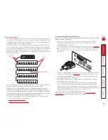
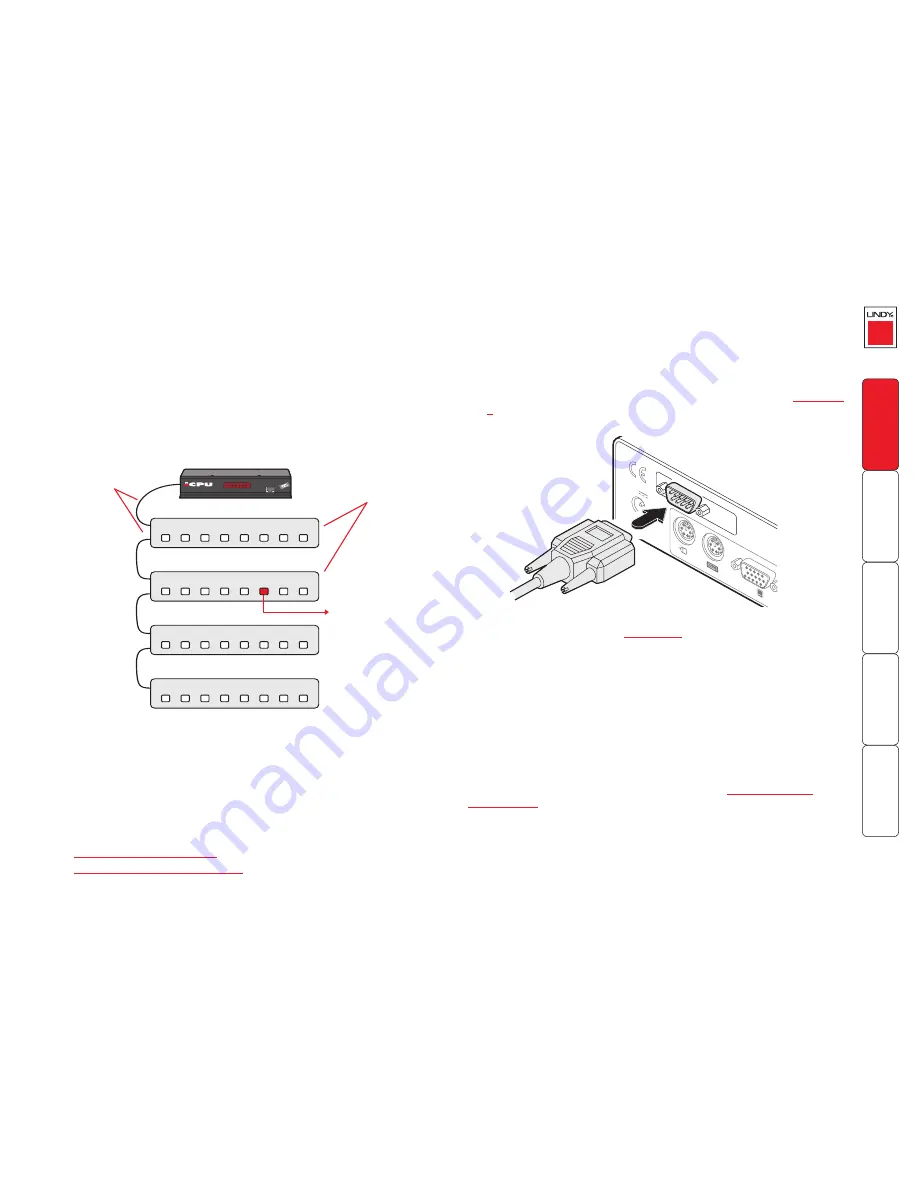
The CPU IP provides a serial port for connection to one or more optional power 
control units. This allows you to control the mains power being supplied to the 
connected host(s) so that an authorised remote user can, if necessary, perform a 
complete cold reboot on a failed host system.
The control connector of the first power switch is connected, via serial cable, to 
the rear panel of the CPU IP. Any additional power switches are then connected 
via a ‘daisy-chain’ arrangement to the first power switch. Each power switch box 
is then given a unique address and access to each power port (4 or 8 ports on 
each power switch box) is gained using a combination of the switch box address 
and the port number. 

COM1

MODE

M

COM2

POWER

CONTROL

INDOOR

USE

ONL

Y

KVM

CONSOLE

5V

1

2

ON

2.5A

COMPUTER

/ KVM

SWITCH

To connect and address the switch boxes

Note: The CPU IP can be powered on during this procedure, however, the switch 
boxes should be switched off.

1  Mount up to four switch boxes in positions where they are close to the 

computers that they will control and not too distant from the CPU IP 
(preferably within 2.5 metres).

2  Use a serial cable with an RJ10 and a 9-pin D-type connector (see 

Appendix 

7

 for specification). Connect the RJ10 plug to the socket marked ‘IN’ on the 

first switch box. Connect the other end to the socket marked ‘COM2’ on 
the CPU IP. 

8

IN

IN

IN

IN

OUT

OUT

OUT

8

8

8

7

7

7

7

6

6

6

6

5

5

5

5

4

4

4

4

3

3

3

3

2

2

2

2

1

1

1

1

LOC REM VNC 100 LNK PWR

IP

Access Switch Plus

Power to computer
Box 2, port 6 - address: 26

Box 1

Box 2

Box 3

Box 4

Power 
switch 
boxes

‘Daisy-chain’ 
control 
connections

The power ports are connected to the power inputs of each computer and the 
power switch box(es) are then connected to a mains power supply.

IMPORTANT: Power switching devices have a maximum current rating. It is 
essential to ensure that the total current drawn by the equipment connected 
to the power switching device does not exceed the current rating of the power 
switching device. You must also ensure that the current drawn from any mains 
socket does not exceed the current rating of the mains socket.

Setting up, configuring and using power switching requires three main steps:

•  Connect and address the switch boxes 

ð

•  

Configure the power strings

•  

Operate remote power switching

3  For each of the remaining switch boxes (if used), use a serial cable with RJ10 

connectors at both ends (see 

Appendix 7

 for specification). Connect one 

end to the socket marked ‘OUT’ of the previous box and the other end to 
the socket marked ‘IN’ of the next box. 

4  Set the addressing switches on each switch box using the micro switches 

according to the switch box manual.

5  Connect IEC to IEC power leads between each port and the power input 

socket of each computer that requires power switching. Carefully note to 
which power ports, on which boxes, each computer is connected. If server 
systems have multiple power inputs, then each input must be connected via 
separate ports, which can be on the same, or different boxes.

6  Connect each box to a suitable mains power input. 

Now proceed to the configuration stage covered in the 

Power switching 

configuration

 section within the Configuration chapter.

Summary of Contents for CPU IP Access Switch Plus

Page 1: ...CPU IP Access Switch Plus User Guide LOC REM VNC 100 LNK PWR IP Access Switch Plus...

Page 2: ...CPU IP in the network 17 Placing CPU IP behind a router or firewall 17 Placing CPU IP alongside the firewall 19 Power switching configuration 20 Performing a flash upgrade 21 Operation Connecting to t...

Page 3: ...nit configuration 46 Advanced unit configuration 47 Network configuration 48 Setting IP access control 49 Serial port configuration 50 Modem port 50 Power control port 50 Host configuration 51 Logging...

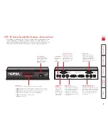
Page 4: ...daptable operation is available across a multitude of systems Note Throughout this manual the LINDY CPU IP Access Switch Plus is referred to simply as the CPU IP KVM switch OR IP network Internet Powe...

Page 5: ...keyboard video and mouse ports of the device to be remotely controlled either a single computer or a KVM switch The USB port on the right is for future expansion and is not currently used Modem port O...

Page 6: ...70058 KVM cables One set per connected computer Part numbers 33711 33718 cable lengths available 1 2 3 5 10 15 or 20 metres Multi platform KVM converter cable Required to connect with computers that u...

Page 7: ...ets plus four screws extend the size of the CPU IP so that it fills the full width of a 1U rack slot COM1 MODE M COM2 PO WER CO NT RO L INDOOR USE ONLY KV 5V 1 2 ON 2 5A COM1 MODE M COM2 PO WER CO NT...

Page 8: ...host computer or KVM switch 1 Ensure that power is disconnected from the CPU IP and the computer or KVM switch to be connected Note If it is not possible to switch off devices prior to connection then...

Page 9: ...twork It can be placed within the local network behind any firewall router connections to the Internet or It can be placed externally to the local network on a separate sub network or with an open Int...

Page 10: ...ote The default serial port speed is 115200K and a standard Hayes compatible auto answer string is sent during startup The default startup string is ATZHS0 1 Both the serial port speed and startup str...

Page 11: ...Plus Power to computer Box 2 port 6 address 26 Box 1 Box 2 Box 3 Box 4 Power switch boxes Daisy chain control connections The power ports are connected to the power inputs of each computer and the pow...

Page 12: ...em config screen Allows you to optionally alter the current settings for the serial port that is used to connect a modem or ISDN terminal adapter The IP addresses are used to emulate a two port networ...

Page 13: ...These should remain set to 5900 and 80 respectively unless they clash with an existing setup within the network See Networking issues for more details When all items are correct select the Save optio...

Page 14: ...n which it might be used and the range of viewer applications that need to view it a number of settings are available that might not make perfect sense at first glance However these settings should al...

Page 15: ...l function If the mouse has a scroll wheel then it is likely to support the IntelliMouse format If it is a Microsoft branded mouse then it will usually state that it is an IntelliMouse on its undersid...

Page 16: ...ion and press 5 Remove power return the mini switch 1 to its OFF position and then re apply power The locally connected monitor should display the first screen of the initial configuration sequence Th...

Page 17: ...3 Click the Configure button in the top right hand corner of the window to display the configuration menu Many of the options within the configuration menu duplicate those that were set or are availa...

Page 18: ...rrectly using only its network address The firewall router must be informed to transfer traffic requesting these port numbers through to the CPU IP When a web server is also on the local network Port...

Page 19: ...CP server and obtain a new address 2 Re enter the same Network configuration screen where the new IP address and network mask should be displayed DNS addressing As with any other network device you ca...

Page 20: ...day to day access Use the latest Secure VNC viewer this has more in built security than is available with the Java viewer To download the viewer Use non standard port numbers Restrict the range of IP...

Page 21: ...N is as follows w x y z Where w is the switch box address first box is 80 second box is 81 etc x is 31 for ON or 32 for OFF y is the power port number from 1 to 8 or 9 to switch all ports z is a check...

Page 22: ...hen power down the CPU IP 8 At the rear of the unit return the mini switch 1 to its OFF position and then re apply power MAC address Media Access Control address this is the unique and unchangeable co...

Page 23: ...ss and hold the hotkeys usually and then press and finally release all three keys Note The and keys when pressed in combination are called hotkeys and they signal to the CPU IP that you wish to contro...

Page 24: ...the hall of mirrors effect IMPORTANT Never configure a system so that your viewer is viewing itself When controlling a host computer using the locally connected keyboard video monitor and mouse it is...

Page 25: ...ion download can take several tens of seconds to complete Once complete a connection details dialog will be displayed 2 In the Server entry type the address of the CPU IP as follows v w x y where v w...

Page 26: ...screen that you are viewing has a larger resolution than your viewing window you will need to scroll around to see all items The viewer window allows you to bump scroll only in full screen mode This m...

Page 27: ...n to display a list of computers 2 Click the required computer name to view and control it Configure This option is displayed only when you are logged on as the admin user When selected it provides ac...

Page 28: ...necessary video information being sent across the link thus improving overall performance Once this has been done providing you use the Hosts button to switch between host computers the video settings...

Page 29: ...ol the remote mouse cursor using a selection of buttons that you click with your local mouse Click to move the remote mouse cursor up down left or right Click to calibrate the remote mouse Click to pr...

Page 30: ...st video output and the remote system video display to achieve the sharpest image Horizontal position Determines the horizontal position of the host screen image within the viewer window Vertical posi...

Page 31: ...actly the same VNC viewer or browser to view the hosts systems This is achieved using PPP Point to Point Protocol and means that you need to use a dial up networking method to initiate the connection...

Page 32: ...fer off This setting will configure an un encrypted link if the CPU IP will allow it otherwise it will be encrypted Prefer on If the CPU IP allows it this setting will configure an encrypted link othe...

Page 33: ...ments Recalibrate the mouse When doing so ensure that the host system does not have mouse cursor trails enabled and that the top left corner of the screen is clear of application windows When logging...

Page 34: ...access the menus IP Access Switch Plus Control Shared Email server Access Mode Host Restore Mouse Functions Return To Host Configuration Logoff Select the Configuration option to display Configuratio...

Page 35: ...e time and date entries Encryption Three options are available Always on prefer off prefer on The one to choose depends on the specific details of your installation see Encryption settings for details...

Page 36: ...this option provides an emergency recovery point MAC address Media Access Control address this is the unique and unchangeable code that was hard coded within your CPU IP unit when it was built It con...

Page 37: ...the serial connection between the CPU IP and a connected modem or ISDN terminal adapter The default setting is 115200 The other communication settings are fixed as No parity 8 bit word 1 stop bit Init...

Page 38: ...1 Use the local keyboard and log on as the admin user 2 Press hotkeys may be different 3 Select Configuration 4 Select Reset configuration WARNING This process will remove all settings and return the...

Page 39: ...possible to exclude all network users and so this option provides an emergency recovery point To clear IP access control 1 Use the local keyboard and log on as the admin user 2 Press hotkeys may be se...

Page 40: ...er of options are available Click here to access the options Colour level This section allows you to select the most appropriate colour level for the speed of the connection to the CPU IP Where the co...

Page 41: ...and host system This is useful for slow connections and you will notice that the remote cursor will catch up with the local cursor roughly once every second Menu key This feature allows you to select...

Page 42: ...If a mismatch is found between the current and the stored identities then a warning will be issued to you If an existing CPU IP is fully reconfigured then it will need to issued with a new identity In...

Page 43: ...m This is necessary because F8 is trapped by the VNC viewer for use as the trigger for this options menu Send Ctrl Alt Del Passes a Ctrl Alt Del sequence to the host system New connection Displays the...

Page 44: ...are available Click here to access the options Inputs View only ignore mouse keyboard When ticked the viewer will not send keyboard or mouse information to the CPU IP or host system Accept clipboard f...

Page 45: ...nfiguration menus Click the Configure button in the top right corner of the window when logged on as the admin user Logged on users Indicates the current users irrespective of whether they are connect...

Page 46: ...ase sensitive and can include certain keyboard symbols The password can be between 1 and 16 characters in length It is important to note however that the password background remains shaded in amber wh...

Page 47: ...be disabled Time and date Use the arrow keys to select the correct time and date The time entry uses the 24 hour clock notation The internal real time clock will continue to run for roughly one week w...

Page 48: ...eived to outgoing data packets If the stated period is exceeded then a connection is considered lost and terminated Background refresh rate Use the arrow keys to alter the refresh rate for screen imag...

Page 49: ...ed alongside the IP address to help define a smaller collection or subnet of devices on a network In this way a distinction is made between locally connected devices and ones that are reachable elsewh...

Page 50: ...e listed higher in the list than any denied addresses Take care not to invoke any deny access settings that would exclude valid users 1 In the access control list click on the entry to be moved 2 Clic...

Page 51: ...stop bit Initialization sequence The codes entered here are used to prepare the connected modem or ISDN terminal adapter for use with the CPU IP The default code is a Hayes compatible string to confi...

Page 52: ...th the required host system The following notations are used means press down the following key means release the following key means add a 250 millisecond delay the entries are not sensitive to case...

Page 53: ...e main menu To get here 1 Using VNC viewer or a browser log on as the admin user 2 Click the Configure button in the top right corner 3 Click the Logging and status option To copy and paste the log Yo...

Page 54: ...ddress section in order to use the telephone system efficiently it is vital for you to know your location relative to the person you are calling In this way you avoid dialling unnecessary numbers When...

Page 55: ...hat the local part of the address is formed by only the last four bits If you use the diagram from the previous example and insert the new net mask it will have the following effect on the final resul...

Page 56: ...omes a little clearer The above mask has the form 11111111 11111111 11111111 11100000 Ignoring the initial three octets the final six zeroes of the mask would ensure that the 32 addresses from 64 0100...

Page 57: ...CPU IP is situated behind a network firewall In order for a remote VNC viewer or web browser to make contact with your CPU IP it is necessary for the firewall to allow communication through a particu...

Page 58: ...ble 5 1 CLK DCD NC NC NC 1 2 DAT RXD 2 5 TXD GND 3 4 GND Female 6 5 4 3 2 1 DTR 4 6 5V DSR 6 7 12V RTS 3 TXD 12V 8 CTS 9 RI 6pin mini DIN female 9pin D type female CPU IP to power switch cable Power s...

Page 59: ...LWin RWin Menu Escape Esc Math operand keys Add Subtract Multiply Central control keys Insert Delete Home End PageUp PageDown Up Down Left Right Print ScrollLock Pause Keypad keys KP_Insert KP_Delete...

Page 60: ...mpt to service the CPU IP yourself Safety considerations when using power switches with CPU IP Follow the manufacturer s instructions when setting up and using power switching products Always ensure t...

Page 61: ...n the equipment and the receiver c Connect the equipment to an outlet on a circuit different from that to which the receiver is connected d Consult the supplier or an experienced radio TV technician f...

Page 62: ...S31015 67451 MUNDOLSHEIM CEDEX France Email france lindy fr Tel 0 825 825 111 Fax 03 88 20 57 74 Italia LINDY Italia Srl Via Varesina 126 B 22079 Villa Guardia CO Italia Email italia lindy it Tel 031...

Page 63: ...ng 21 35 remote setting 48 Dial up connection 30 DNS addressing 18 E Encryption key 12 F Firewall 17 Firmware current version 46 upgrade 21 Flash upgrade 21 Force encryption 34 Full screen mode escape...

Page 64: ...e Defaults local setting 36 RJ10 connector 10 Router 17 S Safety information 59 Screen best resolution 25 navigation 25 Screensaver local setting 34 remote setting 46 Serial port modem connection 9 Se...

Reviews: