Quick Installation Guide
© LINDY ELECTRONICS LIMITED & LINDY-ELEKTRONIK GMBH - FIRST EDITION (Oct 2000)
Please find the complete detailed user manual on the
enclosed CD as PDF File.
Unpacking
Open the shipping carton of the Switch and carefully unpack its contents, the carton should
contain the following items:
o
One 24+2G, 24 port Fast Ethernet Layer 2 Switch.
o
Mounting Kit: 2 mounting brackets and screws
o
Four rubber feet with adhesive backing.
o
One AC power cord.
o
One RS-232 cable
o
This Quick Installation Guide and CD.
Installation
Follow the guidelines below to install the Switch.
o
Do not place any object weighted more than 3Kg (6.6 lb) on the Switch.
o
Connect the power cord to the Switch and the power outlet.
o
Leave at least 10 cm (4 inches) of space around the Switch for heat dissipation.
Desktop or Shelf Installation:
When installing the Switch on the desktop or shelf, please attach the rubber feet to the Switch.
Peel off the protective paper on the pads and attach them on the bottom of the Switch (one at
each corner).
19” Rack Installation:
The 24+2G Switch is rack-mountable and you can install the Switch on an EIA-19 inch
equipment rack. To do this, first install the mounting brackets on the Switch’s side panels (one
on each side), secure them with the included screws, and then use the screws provided with the
equipment rack to mount the Switch on the rack.
Power On the Switch:
The 24+2G Switch has a universal power supply and you can power up the Switch with 90 ~
260V AC, 50 ~ 60Hz power source. The AC power cord connector is located at the rear of the
unit and the On/Off switch is next to the connector. Connect the power cord from the power
outlet to the Switch and push the On/Off Switch to “ON” position to power on the Switch.
After the Switch is powered on, it will perform “self-diagnostic” (POSD). This process takes
about 100 seconds to complete, during this process, the “DIAG” LED will blink green and the
Switch will not response to any configuration program and all the connections to the Switch will
not be available. When the processed is completed, the “DIAG” LED will stay solid green.
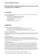
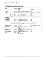
The following table describes the meaning of each LED indicator.


