background image


2-2035 Fisher Dr., Peterborough, ON CANADA K9J 6X6 Ph: (705) 742-1350 or (800) 465-7046   Email: [email protected]   

|


P a g e


LB5155D Series


User Manual


10) 

You can now connect the Optical fiber to the 

OPT IN

 connector on the Rear panel. 


11) 

Turn ON the EDFA & check the LCD display to verify that the System Initialization is in 
process.   


12) 

Remove terminator from the optical output and connect the optical fiber to the 

OPT OUT


connector. 


Note: Always have the power turned OFF when the EDFA input/output are not connected 
or properly terminate unused ports so as to prevent damage to the laser. 


Summary of Contents for LB5155D Series

Page 1: ...LB5155D Series Erbium Doped Fiber Amplifier User Manual ...

Page 2: ...FETY NOTES 2 3 0 LB5155D SERIES FRONT PANELAND BACK PANEL LAYOUT 3 4 0 BLOCK DIAGRAM 4 5 0 TECHNICAL SPECIFICATIONS 4 6 0 INSTALLATION 5 6 1 Required Equipment Tools 5 6 2 Installation of EDFA 5 7 0 OPERATION AND MENU FUNCTIONS 7 7 1 Start Up System Initialization 7 7 2 System Menu 8 7 3 Optical Menu 8 7 4 Pump Menu 8 7 5 Status Menu 9 7 6 DFB Switch 9 7 7 Alarm Confirm Menu 9 8 0 WEB MANAGEMENT S...

Page 3: ... LCD front panel display is used to provide monitoring and associated alarms for all vital parameters If the EDFA operating parameters deviate from the permissible range set by the software the micro processor will alarm the user through the LCD display and the warning LED s will start flickering RED with buzzer sound The LB5155D is equipped with RJ45 and RS232 communication interfaces for system ...

Page 4: ...d laser device that emits invisible light which can permanently damage the retina of an eye Avoid direct exposure to the laser light source Never stare directly into a fiber or at any mirror like surface that could reflect light emitted from an un terminated fiber Never view an active fiber through optical instruments Always ground the EDFA before turning on power grounding resistance should be le...

Page 5: ...K PANEL LAYOUT The LCD front panel display allows you to monitor the EDFA s parameter i e Input output laser power dBm the laser s bias current mA temperature and cooling current mA Check the parameters using the Menu Buttons The DC Power Module has a three screw terminal strip to the 48VDC Fuse replacement should always be with the same type fuse Cartridge type F3AL250V 3 amp 250V ...

Page 6: ...l Input Power 3 10 dBm Optical Output Power 14 24 in 1dBm steps dBm Output Optical power stability 0 2 dB Polarization Sensitivity 0 2 dB PMD 0 5 ps Optical Return Loss 45 dB Optical Connector SC APC or FC APC Optical Fiber Type Single Mode CTB 63 dB CSO 63 dB C N 50 dB Noise Figure 5 0 0dBm Optical Input dB 110 240 VAC 40 70 VDC Power Consumption 50 W Network Interface RS232 or RJ45 480 380 44 W ...

Page 7: ...und the EDFA before turning on power so as to prevent laser and user from static damage 4 Terminate the output port of the EDFA to prevent damage to the laser when not connected to the system 5 Ensure optical jumper connectors are matched properly to the device adapters ie SC APC to SC APC 6 Carefully clean all the fiber optic connectors The suggested way to clean a fiber optic connector is to use...

Page 8: ...the OPT IN connector on the Rear panel 11 Turn ON the EDFA check the LCD display to verify that the System Initialization is in process 12 Remove terminator from the optical output and connect the optical fiber to the OPT OUT connector Note Always have the power turned OFF when the EDFA input output are not connected or properly terminate unused ports so as to prevent damage to the laser ...

Page 9: ...RATION AND MENU FUNCTIONS 7 1 Start Up System Initialization Power up device the LCD panel after loading will show LB5155D xx xx is the output power in dBm You then can use the Menu buttons to navigate through the different menus There are 6 menus that you can use to monitor the EDFA parameters and adjust some parameters See Figure 2 Figure 1 Figure 2 ...

Page 10: ...monitor Input Output Power optical parameters There is also a setting to change the Optical Output power called Power Adj that can adjust the power by 5dB For example for 24 dBm Output EDFA the Power can be adjusted from 19 5dBm to 24 5dBm in 0 1 dB steps Press ENT on Power Adj menu Up Down arrow keys to change value and then again press select to confirm 7 4 Pump Menu In this submenu the Pump par...

Page 11: ...e monitored This submenu will tell you if there is an alarm on any module of the EDFA or if it is operating normally 7 6 DFB Switch The DFB switch is a setting to turn the output of the EDFA ON OFF When the DFB Switch setting is ON the amplified output of the EDFA is available otherwise the output of the EDFA is not available Press ENT on DFB SWITCH menu Up Down arrow keys to switch between ON OFF...

Page 12: ...ual Figure 7 Figure 8 alarm reporting The Alarm buzzer can be turned ON OFF according to your requirements If the Alarm buzzer is ON whenever the EDFA has an alarm Pump Power Supply Input output Optical Power the buzzer makes a beeping sound Irrespective of Alarm buzzer being ON or OFF the alarm however reports on the Front panel the Web GUI ...

Page 13: ...erface Standard RJ45 head as connector pin is defined as follows 1 TX 2 TX 3 RX 4 No Connect 5 No Connect 6 RX 7 No Connect 8 No Connect A green indicator light indicates when the network connection is normal B yellow light flashes to indicate the LAN port is sending data Factory network parameters of the EDFA or they can also be found from the menu functions from front panel of the EDFA or on the...

Page 14: ...s User Manual After logging into the EDFA the home screen of the Web GUI is as shown below The navigation menu is to the left of the page Click on the required menu The EDFA content is displayed for the corresponding menu chosen On the parameters page you can monitor all the EDFA parameters It does not allow to change any parameters ...

Page 15: ... 800 465 7046 Email support lindsaybb com 13 P a g e LB5155D Series User Manual The settings page is as shown next Here you can change the Output Power Turn it ON OFF Shown next is the Network Configuration Page It allows you to change the Network Settings of the EDFA ...

Page 16: ...5D Series User Manual Shown below is the page where you can change user credentials SERIAL COMMUNICATION via RS 232 To serially communicate with the EDFA you will need HyperTerminal or Putty You need to select the COM port that the EDFA is connected to on your computer via serial port And then configure as per below settings ...

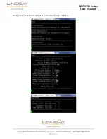
Page 17: ...2035 Fisher Dr Peterborough ON CANADA K9J 6X6 Ph 705 742 1350 or 800 465 7046 Email support lindsaybb com 15 P a g e LB5155D Series User Manual Below is a screenshot of commands for Command Line Interface ...

Page 18: ...2 2035 Fisher Dr Peterborough ON CANADA K9J 6X6 Ph 705 742 1350 or 800 465 7046 Email support lindsaybb com 16 P a g e LB5155D Series User Manual 9 0 WARRANTY RMA POLICY ...

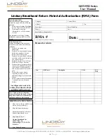
Page 19: ...ETURNS 1 Fill out the Product Return Authorization Form indicating product information Repair items do not require original invoice information but it is helpful to determine warranty eligibility 2 Contact Lindsay Broadband Inc Service Department in one of three ways E mail to contactus lindsaybb com recommended method Include all of the information from the product Authorization Form or Fax the P...

Page 20: ...maged 2 Products are accompanied by a one dollar new purchase for one dollar credit return order 3 Products were purchased within on year from credit return date and are in a current catalog 4 Products are subject to a 10 per RMA and 2 00 per line item 5 Products that are custom made are subject to an additional charge for conversion of not less than 20 and not more than 50 of the FFP price 6 Prod...

Reviews: