Linde BOC Smootharc Advance II MIG 400R Operating Manual Download Page 20

Concave Fillet Weld 

A fillet in which the contour of the weld is below a straight line joining 

the toes of the weld. It should be noted that a concave fillet weld of 

a specified leg length has a throat thickness less than the effective 

throat thickness for that size fillet. This means that when a concave 

fillet weld is used, the throat thickness must not be less than the 

effective measurement. This entails an increase in leg length beyond the 

specified measurement. 
The size of a fillet weld is affected by the electrode size, welding speed 

or run length, welding current and electrode angle. Welding speed and 

run length have an important effect on the size and shape of the fillet, 

and on the tendency to undercut. 
Insufficient speed causes the molten metal to pile up behind the arc 

and eventually to collapse. Conversely, excessive speed will produce 

a narrow irregular run having poor penetration, and where larger 

electrodes and high currents are used, undercut is likely to occur. 

Fillet Weld Data

Nominal Fillet 

Size (mm)

Minimum Throat 

Thickness (mm)

Plate Thickness 

(mm) 

Electrode Size 

(mm)

5.0

3.5

5.0–6.3

3.2

6.3

4.5

6.3–12

4.0

8.0

5.5

8.0–12 & over

4.0

10.0

7.0

10 & over

4.0

Selection of welding current is important. If it is too high the weld 

surface will be flattened, and undercut accompanied by excessive spatter 

is likely to occur. Alternatively, a current which is too low will produce a 

rounded narrow bead with poor penetration at the root. The first run in 

the corner of a joint requires a suitably high current to achieve maximum 

penetration at the root. A short arc length is recommended for fillet 

welding. The maximum size fillet which should be attempted with one 

pass of a large electrode is 8.0 mm. Efforts to obtain larger leg lengths 

usually result in collapse of the metal at the vertical plate and serious 

undercutting. For large leg lengths multiple run fillets are necessary. 

These are built up as shown. The angle of the electrode for various runs 

in a downhand fillet weld is shown on the next page.

Recommended Electrode Angles for Fillet Welds 

Multi-run horizontal fillets have each run made using the same run 

lengths (run length per electrode table). Each run is made in the same 

direction, and care should be taken with the shape of each, so that it has 

equal leg lengths and the contour of the completed fillet weld  

is slightly convex with no hollows in the face. 
Vertical fillet welds can be carried out using the upwards or downwards 

technique. The characteristics of each are: upwards – current used is low, 

penetration is good, surface is slightly convex and irregular. For multiple 

run fillets large single pass weaving runs can be used. Downwards – 

current used is medium, penetration is poor, each run is small, concave 

and smooth (only BOC Smootharc 13 is suitable for this position). 
The downwards method should be used for making welds on thin 

material only. Electrodes larger than 4.0 mm are not recommended 

for vertical down welding. All strength joints in vertical plates 10.0 

mm thick or more should be welded using the upward technique. This 

method is used because of its good penetration and weld metal quality. 

The first run of a vertical up fillet weld should be a straight sealing run 

made with 3.15 mm or 4.0 mm diameter electrode. Subsequent runs 

for large fillets may be either numerous straight runs or several wide 

weaving runs. 

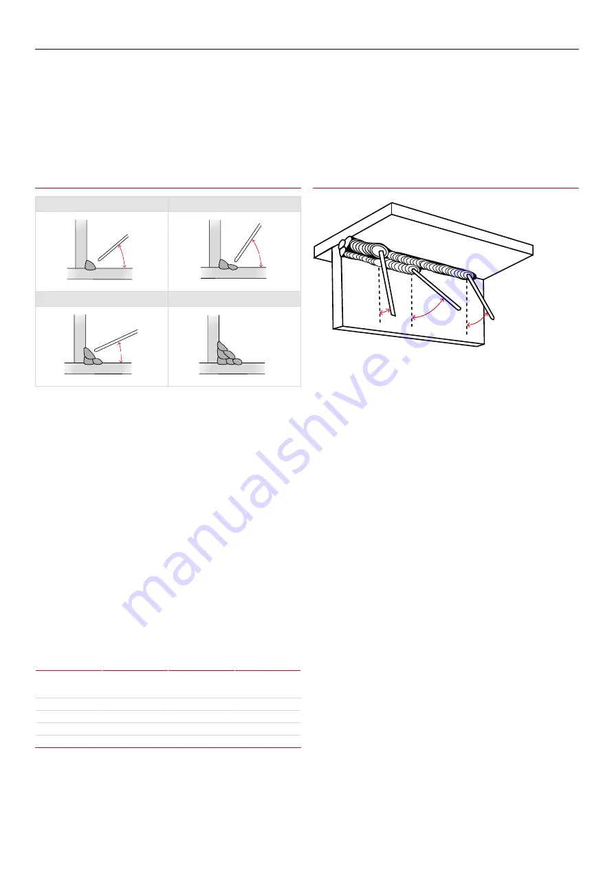
Recommended Angles for Overhead Fillet Welds 

Recommended Electrode Angles for Fillet Welds 

1st Run

2nd Run

Elect

rode

40°

55–60°

20–30°

1

2

3

4

5

6

Elect

rode

40°

55–60°

20–30°

1

2

3

4

5

6

3rd Run

Multi-run Fillet

Elect

rode

40°

55–60°

20–30°

1

2

3

4

5

6

Elect

rode

40°

55–60°

20–30°

1

2

3

4

5

6

30˚

45˚

15˚

20

BOC Smootharc Advance II MIG 400R Operating manual

Summary of Contents for BOC Smootharc Advance II MIG 400R

Page 1: ...MIG 400R Operating manual 6PRRWKDUF GYDQFH GYDQFH...

Page 2: ...he document has been issued Neither BOC nor any of its agents has independently verified the accuracy of the information contained in this document The information in this document is commercial in co...

Page 3: ...nique 21 4 0 General Welding Information 23 4 1 Recommended Welding Parameters 23 5 0 Correct Application Techniques 25 6 0 Package contents 27 7 0 Installation 28 7 1 Installation for MIG MAG process...

Page 4: ...imary terminals and live parts effectively covered Never strike an arc on any gas cylinder Never use oxygen for venting containers Diagram and safety explanation Electrical safety alert Welding electr...

Page 5: ...ys have enough ventilation in confined spaces Be alert to this at all times Keep your head out of the fumes rising from the arc Fumes from the welding of some metals could have an adverse effect on yo...

Page 6: ...sonnel approved by BOC should perform repairs Always disconnect mains power before investigating equipment malfunctions Parts that are broken damaged missing or worn should be replaced immediately Equ...

Page 7: ...res with oxygen or helium mixtures Each gas or gas mixture has specific advantages and limitations Other forms of MIG welding include using a flux cored continuous electrode and carbon dioxide shieldi...

Page 8: ...heir higher deposition rates than solid MIG wires What is often not explained is how they deliver these higher values and whether these can be utilised For example if a solid MIG wire is used at 250 a...

Page 9: ...ates 2 3 Introduction to Metal Cored Arc Welding MCAW How it Works Metal cored arc welding MCAW uses the heat generated by a DC electric arc to fuse metal in the joint area the arc being struck betwee...

Page 10: ...r in FCAW are Dip transfer Globular transfer Spray transfer Pulsed arc transfer operation has been applied to flux cored wires but as yet is not widely used because the other transfer modes are giving...

Page 11: ...ecause of its low density and high thermal conductivity spray transfer in position can be carried out The current flows continuously because of the high voltage maintaining a long arc and short circui...

Page 12: ...ire Material BOC MIG Wire AS2074 C1 C2 C3 C4 1 C4 2 C5 C6 BOC Mild Steel MIG Wire BS3100 AW1 A2 A3 BOC Mild Steel MIG Wire BS1504 430 480 540 BOC Mild Steel MIG Wire ASTM A36 A106 EN8 8A BOC Mild Stee...

Page 13: ...ome grades of self shielded flux cored wires i e E71T 11 E71T GS etc needs to be welded on electrode negative Work return lead fitted to the positive connector Selection of the correct shielding gas T...

Page 14: ...Australia is 50 Hz Hertz 3 2 Welding machine The most important consideration when contemplating the use of arc welding for the first time is the purchase of a suitable welding machine BOC supplies a...

Page 15: ...positions using AC or DC power sources Its easy striking characteristics and the tolerance it has for work where fit up and plate surfaces are not considered good make it the most attractive electrod...

Page 16: ...the current in the middle of the range specified on the electrode package is considered to be the optimum In the case of welding machines with separate terminals for different size electrodes ensure t...

Page 17: ...should be prepared for the joints that suit the application The following section describes the various joint types and areas of application 3 5 Types of joints Butt welds A butt weld is a weld made b...

Page 18: ...60 This preparation provides a ledge on the lower member which tends to retain the molten metal General notes on Butt Welds The first run in a prepared butt weld should be deposited with an electrode...

Page 19: ...mbers are fitted as shown leaving a V shaped groove in which a fillet weld is deposited Fusion should be complete for the full thickness of the metal In practice it is generally necessary to have a ga...

Page 20: ...ally result in collapse of the metal at the vertical plate and serious undercutting For large leg lengths multiple run fillets are necessary These are built up as shown The angle of the electrode for...

Page 21: ...lectrode coating moisture contents Defects caused by welding technique Slag Inclusions Slag inclusions occur when slag particles are trapped inside the weld metal which produces a weaker weld These ca...

Page 22: ...defect can be excessive travel speed electrode size too large welding current too low poor joint preparation letting the weld metal get ahead of the arc Lack of fusion can usually be prevented by redu...

Page 23: ...Wire feed speed m min 3 5 5 0 4 0 7 0 4 0 7 0 4 0 7 0 7 5 9 0 9 0 12 0 8 0 10 0 7 0 9 0 Gas rate flow L min 15 15 15 15 15 15 18 18 Travel speed mm min 350 500 350 500 320 500 280 450 800 1000 420 50...

Page 24: ...eter mm 1 2 1 2 1 6 1 2 1 2 1 6 1 6 Current amps 200 250 300 350 300 400 200 250 175 200 350 400 200 250 Voltage volts 27 29 31 34 30 32 25 28 24 25 29 32 24 26 Wire feed speed m min 6 9 10 0 13 2 16...

Page 25: ...cement 10 Torch positioned at a drag angle of 10 narrow bead with excessive reinforcement Flux cored welding with cored wires takes place normally with the drag technique The welding torch is tilted a...

Page 26: ...rease in temperature has a positive influence in the melt off rate of the wire that will have an influence on the weldbead profile Influence of the change in electrical stickout length on the weldbead...

Page 27: ...455 BOC Argon regulator Work return lead Electrode holder Wire feeder 1 5m 10m inter connecting cable 1 5m 10m inter connecting cable Wire feed rollers Knurled 0 8 0 9 1 0 1 2 1 2 1 6 U Groove 0 8 0...

Page 28: ...ol into the socket at the rear of the power source Fit the wire feed power cable into the front of the machine Attach the earth cable to the rear of the machine Primary current rating This machines ha...

Page 29: ...ar of the power source Repeat this on the wire feeder For select flux cored wire and self shielded wire DCEN Connect the inter connection cable wire feed control into the socket at the rear of the pow...

Page 30: ...se tightly 2 Connect the work return lead into the negative 12 of the machine and fasten it clockwise 3 Please note that for manual metal arc MMA welding the electrode holder can be switched to the ne...

Page 31: ...f all functionalities 8 2 MMA Welding Setup 1 Ensure the machine is correctly plugged into the main circuit 2 Proper PPE must be worn 3 Ensure workplace safety such as fume extraction is in place 4 Fi...

Page 32: ...re to be feed through without the shielding Voltage adjustment The inverter power source allows infinite adjustment of welding voltage even when the arc is struck Wire speed amperage The wire feed con...

Page 33: ...fects reduced spatter heat control has no effect when spray arc welding because there is no more change in current the inductance coil plays no further part A certain amount of inductance with spray t...

Page 34: ...Welding torch overheats Welding torch underrated for welding application Liners Erratic wire feed wire snarls up at outlet guide Liner of incorrect type and size for wire in use worn or dirty liner li...

Page 35: ...KNROL0809 Knurled 1 0 1 2 ADVANCEKNROL1012 Knurled 1 2 1 6 ADVANCEKNROL1216 Aluminium U Groove 0 8 0 9 ADVANCEUROL0809 U Groove 1 0 1 2 ADVANCEUROL1012 U Groove 1 2 1 6 ADVANCEUROL1216 Steel Stainless...

Page 36: ...machine and its consumables 12 1 Power Source Check electrical connections of unit at least twice a year Clean oxidised connections and tighten Inner parts of machine should be cleaned with a vacuum c...

Page 37: ...00A 50 400A Output Voltage 16 5 34V 22 36V Duty cycle 40 400A 45 400A 60 346A 325A Power factor 0 93 Efficiency 85 Wire feeder Remote Wire speed 2 16 m min Wire spool diameter 270mm Wire diameter 0 8...

Page 38: ...d to daily allowances or accommodation and travelling costs NOTE Under the terms of warranty welding torches and their consumables feed drive rollers and feeder guide tubes are not covered Direct or i...

Page 39: ...39 BOC Smootharc Advance II MIG 400R Operating manual...

Page 40: ...of printing Whilst proper care has been taken in the preparation no liability for injury or damage resulting from its improper use can be accepted For more information contact the BOC Customer Engage...

Reviews: