background image

 ovER vIEw


FBC

1 - 4 - 7

7

/34

rev 20-02


„

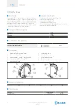
Mechanism type


†

Manual

Blade closing mode

Automatic closing with thermal fuse.
The control mechanism has a thermosensitive element that automatically closes the blade when the temperature in the 
duct exceeds 70°C.
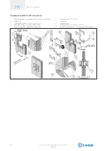
The damper can be closed manually as per the following instructions.

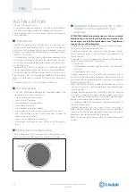
The fire damper is equipped with a spring for closing the blade: pay attention to the hands.

Blade opening mode

Make sure that the damper is open before the ventilation 
system start-up, otherwise there is a risk of product mal-
function.
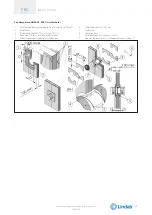
In case of closed damper as a result of the action of the thermosensitive element, it is possible to manually reopen the 
damper once the thermosensitive element has been replaced.
The fire damper can be opened manually as per the following instructions.

The fire damper is equipped with a spring for closing the blade: pay attention to the hands.

Position indication microswitch

on request, the fire damper can be supplied with position microswitch (S1 optional) that signal the closed position of the 
blade. Refer to the section Electrical connections  for more details.

FBC

1 - 4 - 7

7

We reserve the right to make changes without prior notice

Summary of Contents for FBC1

Page 1: ...1812 CPR 1634 CIRCULAR SERIES FBC1 4 7 300 Pa FIRE DAMPER Technical Manual FBC 1 4 7 FBC 1 4 7 lindab we simplify construc tion Technical Manual Installation type with fire resistance class English FIRE DAMPER CIRCULAR SERIES FBC1 4 7 300 Pa Cert N 1812 CPR 1630 1812 CPR 1632 1812 CPR 1634 ...

Page 2: ...This is a 34 page manual ...

Page 3: ...all p 13 Installations within vertical light wall plasterboard p 15 Installations within floor p 20 Installations within vertical wall with Fire Batt Weichschott sealing p 21 Installation within floor with Fire Batt Weichschott sealing p 22 Electrical connections p 23 Electrical wiring p 23 Maintenance and inspections p 24 Periodic inspection and cleaning p 24 Repair p 24 Disposal p 24 Selection p...

Page 4: ...est EN 1366 2 Classification EN 13501 3 Thermal fuse reliability ISO 10294 4 Certifications and approvals CE Certificate of Constancy of Performance FBC1 n 1812 CPR 1630 FBC4 n 1812 CPR 1632 FBC7 n 1812 CPR 1634 Efectis Components 1 Casing made from galvanized carbon steel 2 Air duct connection gasket 3 Intumescent graphite gasket on the outside the casing 4 Intumescent graphite gasket on the insi...

Page 5: ... o W FBC1 FBC1 Floor Installations within floor Floor minimum thickness 150 mm Floor minimum density 550 kg m Mortar sealing ho i o W FBC7 FBC7 FBC4 FBC7 FBC4 FBC1 FBC7 FBC4 FBC1 Floor minimum thickness 100 mm Floor minimum density 550 kg m Mortar sealing ho i o W FBC7 FBC4 FBC7 FBC4 FBC1 FBC7 FBC4 FBC1 W Wet method sealing D Dry method sealing ve Vertical installation ho Horizontal installation i...

Page 6: ... FBC1 FBC7 FBC4 FBC1 Floor minimum thickness 100 mm Floor minimum density 550 kg m Rock wool 140 kg m and endothermic varnish sealing ho i o W FBC7 FBC4 FBC7 FBC4 FBC1 FBC7 FBC4 FBC1 W Wet method sealing D Dry method sealing ve Vertical installation ho Horizontal installation i o Origin of fire irrelevant Pa Pascal of depression E Integrity I Thermal insulation S Smoke seal Cert N FBC1 1812 CPR 16...

Page 7: ...start up otherwise there is a risk of product mal function In case of closed damper as a result of the action of the thermosensitive element it is possible to manually reopen the damper once the thermosensitive element has been replaced The fire damper can be opened manually as per the following instructions The fire damper is equipped with a spring for closing the blade pay attention to the hands...

Page 8: ...02 Temperature calibration of thermosensitive element for automatic damper closing 70 C 7 C Closing by remote control Not available Motorized version Not available FBC 1 4 7 8 We reserve the right to make changes without prior notice ...

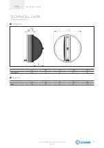
Page 9: ...20 02 TECHNICAL DATA The sizes shown are in mm Dimension Ø mm 100 125 160 200 S blade exposition mm 21 34 51 72 Weights Ø mm 100 125 160 200 Weight kg 0 2 0 3 0 4 0 6 FBC 1 4 7 9 We reserve the right to make changes without prior notice ...

Page 10: ...re damper can be installed with the blade axis posi tioned vertically or horizontally or tilted at any angle Installation of flexible connectors in order to balance out the ventilation ducts expansion ATTENTION thefollowingindicationsaretobeconsidered binding only in the case in which in the country where the fire dampers are installed legislation or local regulations require the use of flexible j...

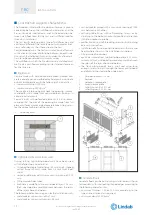
Page 11: ... 02 Minimum distances In accordance with Articles 7 and 13 of EN 1366 2 respect the minimum distances indicated below Minimum distances 1 Vertical lateral wall 2 Floor FBC 1 4 7 11 We reserve the right to make changes without prior notice ...

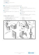
Page 12: ...d with the following characteristics U shaped horizontal metal frame 50 mm and C shaped vertical frame 49 mm made from 0 6 mm thick sheet metal vertical profiles placed with a maximum spacing of 1000 mm Filling made of rock wool Each side is made from two plasterboard layers 12 5 mm thick unalinged to avoid alignment between the joints of the layer above and below The following indications are giv...

Page 13: ...wing Filling Fill the space between ventilation duct and wall as indicat ed in the drawing Insulation Apply the mineral fiber gaskets supplied with the damper at a distance of 15 mm from the seal Fire damper model FBC1 1 Plasterboard arch infill thickness 12 5 mm 2 Rock wool 100 kg m or mortar or plaster putty 3 Ventilation duct 4 Fire damper 5 Self drilling screw Ø 3 5 X 45 mm 6 Mineral fiber gas...

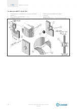
Page 14: ...er min 50 to nominal diameter max 70 Fire damper model FBC4 FBC7 1 Fire damper 2 Rock wool 100 kg m or mortar or plaster putty 3 Self drilling screw Ø 3 5 X 45 mm 4 Mineral fiber gasket supplied with the damper 5 Plasterboard arch infill thickness 12 5 mm 6 Ventilation duct 7 Vertical rigid wall minimum density 550 kg m D from nominal diameter min 50 to nominal diameter max 70 FBC 1 4 7 14 We rese...

Page 15: ...n duct and wall as indicat ed in the drawing Insulation Apply the mineral fiber gaskets supplied with the damper at a distance of 15 mm from the seal Fire damper model FBC1 square hole 1 Wall rock wool density according to fire resistance class of the wall 2 Plasterboard arch infill thickness 12 5 mm 3 Type A EN 520 plasterboard thickness 12 5 mm 4 Sealing rock wool 40 kg m or mortar or plaster pu...

Page 16: ...sistance class of the wall 2 Metal frame 3 Type A EN 520 plasterboard thickness 12 5 mm 4 Mortar or plaster putty 5 Mineral fiber gasket supplied with the damper 6 Fire damper 7 Ventilation duct D from nominal diameter min 50 to nominal diameter max 70 FBC 1 4 7 16 We reserve the right to make changes without prior notice ...

Page 17: ...ealant 3 Plasterboard thickness 12 5 mm F type EN 520 4 Rock wool 40 kg m or mortar or plaster putty 5 Mineral fiber gasket supplied with the damper 6 Metal frame 7 Ventilation duct 8 Fire damper 9 Plasterboard arch infill thickness 12 5 mm 10 Self drilling screw Ø 3 5 X 45 mm D from nominal diameter min 50 to nominal diameter max 70 FBC 1 4 7 17 We reserve the right to make changes without prior ...

Page 18: ...board thickness 12 5 mm F type EN 520 4 Rock wool 100 kg m or mortar or plaster putty 5 Mineral fiber gasket supplied with the damper 6 Self drilling screw Ø 3 5 X 45 mm 7 Fire damper 8 Ventilation duct 9 Plasterboard arch infill thickness 12 5 mm D from nominal diameter min 50 to nominal diameter max 70 FBC 1 4 7 18 We reserve the right to make changes without prior notice ...

Page 19: ...rboard thickness 12 5 mm F type EN 520 4 Rock wool 100 kg m or mortar or plaster putty 5 Mineral fiber gasket supplied with the damper 6 Self drilling screw Ø 3 5 X 45 mm 7 Fire damper 8 Ventilation duct 9 Plasterboard arch infill thickness 12 5 mm D from nominal diameter min 50 to nominal diameter max 70 FBC 1 4 7 19 We reserve the right to make changes without prior notice ...

Page 20: ...hown in the drawing Filling Fill the space between ventilation duct and wall as indicat ed in the drawing Insulation Apply the mineral fiber gaskets supplied with the damper at a distance of 15 mm from the seal Fire damper model FBC1 FBC4 FBC7 1 Mineral fiber gasket supplied with the damper 2 Fire damper 3 Mortar 4 Ventilation duct 5 Floor minimum density 550 kg m D From nominal diameter min 0 to ...

Page 21: ...f 50 mm and minimum den sity of 140 kg m The panels must be covered on both faces of the wall with endothermic varnish type PROMASTOP E PASTE or HILTI CFS CT minimum thickness of 1 mm and with an internal perimeter sealant type PROMASTOP E PASTE or HILTI CFS S ACR minimum thickness of 1 mm Insulation Apply the mineral fiber gaskets supplied with the damper at a distance of 15 mm from the seal Fire...

Page 22: ...50 mm and minimum density of 140 kg m The panels must be covered on both faces of the wall with endothermic varnish type PROMASTOP E PASTE or HILTI CFS CT minimum thickness of 1 mm and with an internal perimeter sealant type PROMASTOP E PASTE or HILTI CFS S ACR minimum thickness of 1 mm Insulation Apply the mineral fiber gaskets supplied with the damper at a distance of 15 mm from the seal Fire da...

Page 23: ...elements Never switch on the power supply during electrical connections Wiring diagram for position microswitches FCU Closed damper contact A The fire damper s blade is open the air flow is allowed B The fire damper s blade is closed the air flow is not allowed 4 Normally opened BLUE 1 Common neutral BLACK 2 Normally closed GREY 1mA 4V AC min 6A 250V AC max FBC 1 4 7 23 We reserve the right to mak...

Page 24: ...onstruction sup port Damper cleaning is included in the ordinary maintenance activities of the ventilation ducts Fire dampers can be cleaned with a dry or wet cloth In the case of resistant dirt it is possible to use normal household detergents If prescribed for the type of building it is possible to use disinfectant detergents It s not allowed to use abrasive detergents or mechanical abrasive cle...

Page 25: ... 20 Pa ΔP 30 Pa ΔP 40 Pa Q Lw Q Lw Q Lw mm m h dB A m h dB A m h dB A 100 78 34 6 96 39 7 112 43 5 125 160 37 6 196 42 2 226 45 4 160 357 39 5 437 44 7 504 48 4 200 756 43 7 922 48 4 1061 51 8 Air flow rates as a function of generated sound levels Ø Lw 30 dB A Lw 35 dB A Lw 40 dB A Q ΔP Q ΔP Q ΔP mm m h Pa m h Pa m h Pa 100 65 14 1 79 20 5 97 30 3 125 114 10 2 143 16 0 178 24 9 160 246 9 4 299 14 ...

Page 26: ...graph Ø Lw 30 dB A Lw 35 dB A Lw 40 dB A Q ΔP Q ΔP Q ΔP mm m h Pa m h Pa m h Pa 100 65 14 1 79 20 5 97 30 3 125 114 10 2 143 16 0 178 24 9 160 246 9 4 299 14 0 364 20 8 200 423 6 1 523 9 4 645 14 5 FBC 1 4 7 26 We reserve the right to make changes without prior notice ...

Page 27: ...0 6 9 5 2 4 4 4 6 5 6 7 6 1000 8 3 7 3 6 7 6 6 7 7 8 2000 11 4 8 1 6 1 5 3 5 8 7 5 4000 8 9 9 8 8 8 2 7 3 6 1 8000 5 3 10 5 13 13 10 3 5 1 Ø160 Speed m s Hz 2 4 6 8 10 12 63 14 1 5 3 1 3 5 6 7 7 7 6 125 6 2 1 3 2 5 5 3 7 1 7 8 250 1 1 2 6 4 5 1 5 9 500 4 8 4 5 4 5 4 8 5 5 6 4 1000 7 9 7 6 7 5 7 5 7 8 8 2 2000 10 8 8 1 6 4 5 6 5 7 6 8 4000 11 9 4 8 2 7 3 6 7 6 5 8000 2 4 8 8 12 5 13 3 11 3 6 6 Ø200...

Page 28: ...IES AND SPARE PARTS Arch infill panels for plasterboard installation from Ø 100 to Ø 200 thickness 12 5 mm TAMP WH25 Ø Closed damper microswitch FBCFC Thermofuse with 70 C setting for FBC FBC70 FBC 1 4 7 28 We reserve the right to make changes without prior notice ...

Page 29: ... valve Position indication microswitches S0 Without position microswitch S1 With position indication microswitch Dimension XYZ Nominal diameter mm Examples Code Fire damper EI 120 S without valve and without microswitch Ø 200 FBC7 S0 200 Fire damper EI 60 S without valve and without microswitch Ø 100 FBC1 S0 100 Fire damper EI 90 S without valve and with microswitch Ø 125 FBC4 S1 125 FBC 1 4 7 29 ...

Page 30: ...n vertical rigid walls made from aerat ed concrete blocks standard concrete or masonry with a minimum thickness of 100 mm and minimum density of 500 kg m Installation within light plasterboard walls with mini mum thickness of 100 mm Installation within concrete floors or aerated concrete with minimum thickness 100 mm FBC1 FBC4 or 150 mm FBC7 and minimum density 550 kg m Installation with Fire Batt...

Page 31: ...on Index FBC 1 4 7 31 34 rev 20 02 REVISION INDEX Revision n Date of issue Description 19 11 2019 11 First issue 20 02 2020 02 Ø180 remove FBC 1 4 7 31 We reserve the right to make changes without prior notice ...

Page 32: ......
Page 33: ...antly improving its products the aesthetic or dimensional features the technical data the equipment and accessories indicated could be subject to variations www lindab com Fire dampers are manufactured by MP3 Srl www mp3 italia it ...

Page 34: ...ts and solutions that are easy to use as well as offering efficient availability and logistics We are also working on ways to reduce our impact on our environment and climate We do that by developing methods to produce our solutions using a minimum of energy and natural resources and by reducing negative effects on the environment We use steel in our products It s one of few materi als that can be...

Reviews: