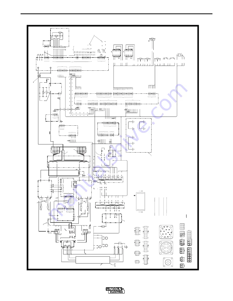
Lincoln INVERTEC STT 2 Operator'S Manual Download Page 29

F-1

DIAGRAMS

F-1

INVERTEC STT II

R

32A

32B

15

16

J22

R

B

18V

32C

43A

R

U

3

18V

501

B

504

W

4

5

5

275

1

8

6

3

311

10

J6

1

212A

9

7

212

352

212B

503A

Y

301

305

245

223

8

11

3

1

3

503

24V

351

244

CASE

CASE

BACK

PLATFORM

4 AMP

S

BOTTOM

S

OUTSIDE

I

YY

4,5

12D

N

O

O

12

H3

H1

 FAN

SLOW

12B

RIGHT

MOTOR

BLOW

H1

1

J11

6

5

379

2

J9

CR2

H3

3

4

2W

10K

CW (MAX)

353

362

363

CONTROL

BACKGROUND

2

12

6

7

4

10

3

N.L.

ASSEMBLY

  INPUT

LINE

POWER

LINE

LOAD

D

C

B

A

F

S1

POWER

OFF

W

ON

U

A

INPUT 

PER 

R

N.A.

V

B

B

W

C

G

C

B

C

A

B

FILTER

A

52

TRIGGER

CORE

3

1

7

5

6

8

2

4

8

7

14

12C

12D

- ARC

+ ARC

CURRENT

METER

VAC

12D

A

378

11

363

J4

CW (MAX)

11

22

33

44

5

6

5

359

358

2W

10K

R11

3

5

377

5

6

6

TRANSFORMER

D1

O

374

N

I

O

T3

  CURRENT

N

2

5

N.E.

4

371

1

3

4

3

10

J5

R

210

211A

502

246

212C

J3

6

B

Y

9

364

365

366

2

5

1

367

369

368

W

B

2

4

12

9

1

5

7

8

9

13

10

1

J28

10

11

8

9

7

5

8

10

5

3

1

4

2

4

6

6

J33

2

372

372

4

371

5

J1

6

7

J27

2

376

R

1

1

4

370

370

376

374

371

B

3

8

12

115V

374

10

1

32

2

33B

8

7

33A

J26

B

3

E

R

B

W

4

290A

1

10

367A

369

.045

502

(-)

INDICATOR

J25

115

223

357

356

5

355

6

354

6

2

1

CB2

J37

403

504

TRANSFORMER

 AUXILIARY

T1

 AUXILIARY

T4

N.D.

TRANSFORMER

13

1

501

220-

212A

150 5W

4

0V

H3

H2

H1

H1

9A

9A

9D

9A

PROTECTION

13

9C

R

W

S7

RECONNECT

1

12B

12B

212C

287

43A

R

18V

4

13

359

7

14

2

356

358

355

354

357

352

16

10

351

360

15

353

361

2

1

362

244

303

303

242

302

371A

302

374A

304

304

275

305

243

2

301

4

240

241

DARLINGTON

12

52

2

12D

2

4

W

1

D3

4

S

F

5

D4

1

BOARD

3

J16

TOP

D5

5

7

DRIVER

F

12B

MOTOR

 FAN

LEFT

H1

MOTOR

TOP

H3

 FAN

H1

H3

H1

   D13

RECTIFIER


TP2

TP1

-

TP3

9D

J16, J28

 J34

A

N.K.

413

416

405

408

406

VAC

1

VAC

7

3

4

3

2

1

F

8

52

314

315

J13

ELECTRODE SENSE LEAD

360

367

S2

VAC

368

367A

STAINLESS

R12

42

S3

.035

INTERFACE

503

TRIGGER

MILD

378

PEAK

377

PEAK

METER

BACKGROUND

CONTROL

HOT START

CW

WIRE TYPE

2W

500K

TAILOUT

CONTROL

R14

N.J.

REMOTE

1

5

407

2

6

6

3

115

350

J35

9

12

11

6

J17

J23

J24

METER PINOUT (VIEWED FROM BACK OF METER) 

ELECTRICAL SYMBOLS PER E1537

W

18V

N

J2

2

J23

Y

380-

4

415V

H3

1

H2

H3

230V

200-

208V

N.M.

BACK

FOR SINGLE PHASE INPUT: CONNECT GREEN LEAD TO GROUND PER NATIONAL ELECTRIC CODE.

6V

10V

J24

18V

THERMOSTAT

COLOR CODE:

U

FAN

U

Y

WRAP RED LEAD WITH TAPE TO PROVIDE 600V. INSULATION.

J26

CONNECT BLACK & WHITE LEADS TO SUPPLY CIRCUIT.

B = BLACK

CASE

TRAY

G = GREEN

N = BROWN

FRONT

NOTES:

O = ORANGE

R = RED

W = WHITE

N.A.

J25

Y = YELLOW

U = BLUE

1. FOR MACHINES SUPPLIED WITH INPUT CABLE

N.M.  PRESENT ON EUROPEAN VERSIONS, CODE 10383 AND HIGHER.

FOR SINGLE PHASE INPUT: GROUND MACHINE PER NATIONAL AND LOCAL ELECTRICAL CODES.

CONNECT TERMINALS U, V & W TO SUPPLY CIRCUIT.

CONNECT TERMINALS U & W TO SUPPLY CIRCUIT.

FOR THREE PHASE INPUT: GROUND MACHINE PER NATIONAL AND LOCAL ELECTRICAL CODES.

N.B.  SINCE COMPONENTS OR CIRCUITRY OF A PRINTED CIRCUIT BOARD MAY CHANGE WITHOUT AFFECTING


COMPONENTS OR CIRCUITRY HAVING A COMMON CODE NUMBER.

THE INTERCHANGEABILITY OF A COMPLETE BOARD, THIS DIAGRAM MAY NOT SHOW THE EXACT

CONNECTION SHOWN IS FOR 440-460V OPERATION.

N.D.  PLACE "A" LEAD ON APPROPRIATE CONNECTION FOR INPUT VOLTAGE.

N.E.  D1 THRU D5 OUTPUT DIODES ARE A MATCHED SET.

D7 THRU D11 OUTPUT DIODES ARE A MATCHED SET.

9

N.F.  R1, R9 BLEEDER RESISTORS ARE A MATCHED SET.


J21

1

N.G.  C1, C2 CAPACITORS ARE A MATCHED SET.


P21

2

PINOUT OF FRONT PANEL CONNECTORS (REAR VIEW)

3

4

3

5

J29. J31

2

CONNECTION SHOWN IS FOR 380-460V OPERATION.

6

N.H.  PLACE SWITCH IN APPROPRIATE POSITION FOR INPUT VOLTAGE.

1

6

N.I.          DENOTES A TWISTED WIRE PAIR OR GROUP. 

1

5

P29, P31

2

4

3

J30

4

3

5

2

6

1

P30

6

1

1

5

J22

9

FOR THREE PHASE INPUT: CONNECT GREEN LEAD TO GROUND PER NATIONAL ELECTRIC CODE.

2

2

4

3

2

N.K.  NOT PRESENT ON EUROPEAN VERSIONS, CODE 10309 AND HIGHER.

4

1

10

5

3

11

4

6

12

N.L.  PRESENT ON EUROPEAN VERSIONS, CODE 10309 AND HIGHER.

4

13

8

3

14

P22

15

8

16

7
6
5

16

4

15

3

14

2

13

1

12
11

10

7

J38

J19

N.J.  NOT PRESENT ON EUROPEAN VERSION.

2. FOR MACHINES NOT SUPPLIED WITH INPUT CABLE

CONNECT BLACK, RED & WHITE LEADS TO SUPPLY CIRCUIT.

J39

1

2

3

4

310

309

310A

310

309A

309A

310A

2

6

J7

224A

10

2W

309

INSIDE

12B

25W

+

2200 F

C1

-

BOARD

25

450V

R4

(RIGHT)

3

4

1

5

307

2
3

6

308

J10

8

9D

4

52

52

2

B

2

9

J34

J36

C4

2W

R3

10

.001/400

N.E.

5

W

12C

12A

S

F

OUTSIDE

TOP

CHOKE

BOARD

3

12A

J12

J8

14

N.H.

BOARD

224

R

310

J15

316

9B

9B

12B

401, 403

1, 8

8

371

J22

51

12B

12B

TOP

12B

.001/400

CR1

25

2200 F

450V

9A

25W

-

+

53

9A

+

N.G.

9

R6

12A

R7

12A

12

R

W

R

W

401, 403

402, 404

(LEFT)

BOARD

SWITCH

1, 8

25W

25

4, 5

I

21

WIRE

81

82

GND

4

2

42

41

FEEDER

32

31

J39

N

B

H

L

M

42

414

B

H1

+

C

4

3

2

J

A

8

12

TRANSFORMER

C8

288

4

2  300W

289

R16

288A

SENSE

C2

L3

4

MAIN 

1

3

289A

20/400

D11

T2

2

J18

4

F

S

4

313

3

3

2

J14

210A

210

THERMOSTAT

CHOKE

FAN

CASE

BOTTOM

1

1

S


INSIDE

F

BOTTOM

D9

BOTTOM

D10

1

14

311

53

3

4

33C

N

J30

33

1

2

6

6

224

H6

H4

A

440-

460V

A

5

9

J31

42V

H5

H4

115V

J21

R15

C

E

2  300W

G

J38

409

A

412

D

404

CURRENT

F

411

291

H

GND

B

MODULE

B

R

DRIVE

BOARD

14

317

9

9B

9B

402, 404

+

N.G.

N.F.

R5

25

25W

25W

7500

R9

9B

SWITCH

SHROUD

J6, J27, J33

J2, J36

J18, J37

J11, J12, J14

J1, J8,

P.C. BOARD CONNECTOR CAVITY NUMBERING SEQUENCE

212B

32C

33C

D12

J3, J9,

DARLINGTON

E

B

B

402

W

401

W

C

J

410

10K

PB

10K

OPTIONAL

D

CB1

C

76

75

6AMP

F

G

43B

42

9A

9D

9C

3

4

5

BOARD

POWER

8

309

7

308

307

W

14

THERMOSTAT

W

HEATSINK

J22

503A

DARLINGTON

503B

242

243

241

240

374A

371A

11

211A

9

350

5

R1

25W

7500

N.F.

D7

D8

R2

1

2

W

D2

C3

3

53

14

J5, J7,

(VIEWED FROM COMPONENT SIDE OF BOARD)

J15, J35

J10, J13,

J4, J17

E

1

I

3

4

77

K

Y

R13

(+)

10K

2

2W

CW (MAX)

3

361

CONTROL

366

503A

WIRE SIZE

THERMAL

OVERLOAD

364

365

7

6

8

5

16

13

15

14

4

12

11

CONTROL

CURRENT

BOARD

415

31A

33D

6AMP

4

6

246

245

212

2

INLINE CONNECTOR CAVITY NUMBERING SEQUENCE

313


    G3136

           WIRING DIAGRAM - INVERTEC STT  II        

(VIEWED FROM WIRE SIDE OF CONNECTOR)

1-9-98B

BG

SENSE

(-)

VOLTAGE

CONNECTION

(+)

2

1

J19

290

PROTECTION BOARD

REMOTE

288B

TOROIDAL

289B

374

3

51

H5

6

51

9B

N.L.

H

N

K

I

B

G

J

A

F

L

M

H

C

A

E

G

D

I

4

F

B

J

E

3

C

2

D

1

NOTE:  This diagram is for reference only.   It may not be accurate for all machines covered by this manual.  The specific diag

ram for a particular code is pasted inside

the machine on one of the enclosure panels.  If the diagram is illegible, write to the Service Department for a replacement.  G

ive the equipment code number..

Summary of Contents for INVERTEC STT 2

Page 1: ... OPERATE OR REPAIR THIS EQUIPMENT WITHOUT READ ING THIS MANUAL AND THE SAFETY PRECAUTIONS CON TAINED THROUGHOUT And most importantly think before you act and be careful For use with machines having Code Numbers 10381 10382 10383 Sales and Service through Subsidiaries and Distributors Worldwide Cleveland Ohio 44117 1199 U S A TEL 216 481 8100 FAX 216 486 1751 WEB SITE www lincolnelectric com World ...

Page 2: ...R WEARERS SHOULD CONSULT WITH THEIR DOCTOR BEFORE OPERATING Read and understand the following safety highlights For additional safety information it is strongly recommended that you purchase a copy of Safety in Welding Cutting ANSI Standard Z49 1 from the American Welding Society P O Box 351040 Miami Florida 33135 or CSA Standard W117 2 1974 A Free copy of Arc Welding Safety booklet E205 is availa...

Page 3: ...rical earth ground 3 f Maintain the electrode holder work clamp welding cable and welding machine in good safe operating condition Replace damaged insulation 3 g Never dip the electrode in water for cooling 3 h Never simultaneously touch electrically hot parts of electrode holders connected to two welders because voltage between the two can be the total of the open circuit voltage of both welders ...

Page 4: ...event the welding sparks from starting a fire Remember that welding sparks and hot materials from welding can easily go through small cracks and openings to adjacent areas Avoid welding near hydraulic lines Have a fire extinguisher readily available 6 b Where compressed gases are to be used at the job site special precautions should be used to prevent hazardous situations Refer to Safety in Weldin...

Page 5: ...s et non inflammables 4 Des gouttes de laitier en fusion sont émises de l arc de soudage Se protéger avec des vêtements de protection libres de l huile tels que les gants en cuir chemise épaisse pan talons sans revers et chaussures montantes 5 Toujours porter des lunettes de sécurité dans la zone de soudage Utiliser des lunettes avec écrans lateraux dans les zones où l on pique le laitier 6 Eloign...

Page 6: ...ine Carton and Equipment For Damage Immediately When this equipment is shipped title passes to the purchaser upon receipt by the carrier Consequently Claims for material damaged in shipment must be made by the purchaser against the transportation company at the time the shipment is received Please record your equipment identification information below for future reference This information can be f...

Page 7: ...ating Controls B 2 Design Features and Advantages B 2 Welding Capability B 2 Limitations B 2 Operational Features and Controls B 3 Welding Operation B 4 Welding Parameters and Guidelines B 5 Welding Procedures for Steel Horizontal Fillet B 5 Welding Procedures for Stainless Steel Horizontal Fillet B 6 Accessories Section C Options Accessories C 1 LN 742 or STT 10 Wire Feeder Connection Instruction...

Page 8: ... 6 mm2 10 6 mm2 460 60 30 16 10 6 mm2 10 6 mm2 200 50 60 40 33 10 6 mm2 10 6 mm2 220 50 60 40 30 10 6 mm2 10 6 mm2 380 50 60 30 18 10 6 mm2 10 6 mm2 415 50 60 30 17 10 6 mm2 10 6 mm2 440 50 60 30 16 10 6 mm2 10 6 mm2 HEIGHT WIDTH DEPTH WEIGHT 23 2 in 13 2 in 24 4 in 100 lbs 589 mm 336 mm 620 mm 46 kg OUTPUT DUTY CYCLE AMPS VOLTS AT RATED AMPS 60 Duty Cycle 225 29 100 Duty Cycle 200 28 CURRENT RANG...

Page 9: ...trical codes SUPPLY CONNECTIONS Be sure the voltage phase and frequency of the input supply is as specified on the rating plate Input Power supply line entry in provided on the case back of the machine See figure A 1 for location of the rating plate The Invertec STT II should be connected only by a qualified electrician Installation should be made in accordance with local and national codes Refer ...

Page 10: ...ntry access hole at the right rear of the machine 3 Route the cable through the cable hangers located along the lower right inside edge of the machine up to the power switch located on the front panel 4 Strip away 102 mm 4 in of the outer jacket Trim fillers and strip conductor jackets to connect to the power switch 5 Connect the three phase line con ductors to the power switch termi nals labeled ...

Page 11: ...AC 1 Open reconnect panel access door on wrap around 2 Move input voltage switch to Voltage 380 460V pos ition 3 Move lead A to 440 460 Terminal 380 or 415 VAC 1 Open reconnect panel access door on wrap around 2 Move input voltage switch to Voltage 380 460V position 3 Move lead A to 380 415 Terminal 220 or 230 VAC 1 Open reconnect panel access door on wrap around 2 Move input voltage switch to Vol...

Page 12: ...out of fumes Use ventilation or exhaust to remove fumes from breathing zone WELDING SPARKS can cause fire or explosion Keep flammable material away Do not weld on containers that have held combustibles ARC RAYS can burn Wear eye ear and body protection OPERATING INSTRUCTIONS Read and understand entire section before operating machine GENERAL WARNINGS SAFETY PRECAUTIONS Observe additional Safety Gu...

Page 13: ... Digital meters for procedure settings are standard Automatic Inductance or Pinch Control Solid state circuitry for extra long component life Current feedback ensures that original procedure settings all remain constant Arc Sense lead assembly Electrode and Work connects through a 4 pin case front connector Peak Current and Background Current may be remotely controlled Thermostat and FET over curr...

Page 14: ...EAK CURRENT DISPLAY METER This is a digital meter for displaying the preset Peak Current This meter displays in 1 amp increments This meter does not indi cate actual welding current only the preset current 4 HOT START CONTROL POTENTIOMETER Hot Start provides approximately 25 to 50 more current during the initial start of the weld for improved arc starting and bead appearance This control adjusts t...

Page 15: ...er connection instructions 11 ARC SENSE RECEPTACLE This is a four pin MS type connector for WORK and ELECTRODE sense leads The STT requires a WORK sense and ELECTRODE sense lead for proper operation The ELECTRODE sense lead is bolted together with power source electrode lead at the wire feeder gun block The WORK sense lead is furnished with an alligator type clip for connection to the work piece R...

Page 16: ...vel should be set greater than in a cor responding application using a gas blend with a high percentage of Argon Longer initial arc lengths with 100 CO2 are required to reduce spatter BACKGROUND CURRENT The Background Current provides the control for the overall heat input to the weld Adjusting this level too high will cause a large droplet to form and globular type transfer to occur resulting in ...

Page 17: ...Electrode size mm 0 035 0 045 0 045 0 9 1 1 1 1 WFS min m min 100 100 120 2 5 2 5 3 0 Peak Current 225 270 310 Background Current 40 65 70 Tailout setting 8 4 6 Average Amperage 70 110 130 Travel Speed min 12 12 12 m min 0 3 0 3 0 3 Gas Flow cfh L min 25 12 Electrical Stickout 1 4 3 8 mm 6 4 10 45 END VIEW 75 FRONT VIEW DIRECTION OF TRAVEL 75 TOP VIEW DIRECTION OF TRAVEL Plate Thickness mm 20 ga 1...

Page 18: ...tely sense arc voltage One set is required for each STT II power source A 10 ft and 25 ft set are provid ed as standard with the machine Additional sets are available in 10 ft K940 10 25 ft K940 25 and 50 ft K940 50 lengths K942 1 REMOTE CONTROL Allows remote adjust ment of Peak and Background Current settings REMOTE RECEPTACLE For optional remote interface Connection to the STT 10 Wire Feeder or ...

Page 19: ...ire feeder control cable between the LN 742 or STT 10 and the 14 pin Wire Feeder Receptacle on the STT II For the STT 10 Wire Feeder Connect the second wire feeder control cable between the STT 10 and the 10 pin Remote Receptacle on the STT II M17657 ARC SENSE LEAD ELECT CONNECT ELECTRODE LEAD AND ELECT ARC SENSE LEAD TOGETHER TO ELECTRODE TERMINAL OF WIRE FEEDER ELECTRODE LEAD Only qualified pers...

Page 20: ...ENSE LEAD ELECT CUT OFF WITHIN 6 INCHES WIRE FEEDER TAPE ARC SENSE ELECT REMOTE ELECTRODE LEAD WORK LEAD TO THE WELDING ARC ELECTRODE LEAD STT 10 WIRE FEEDER WARNING Turn off input power to the Welding Power source using the disconnnect switch at the fuse box before connecting the wire feeder Only qualified persons should install ELECTRIC use or service this machine SHOCK CAN KILL WIRE ARC SENSE L...

Page 21: ... with machine NEVER USE A SHORTING STRAP FOR THIS PROCE DURE 5 Locate the two capacitor terminals large hex head cap screws shown in Figure D 1 6 Use safety glasses electrically insulated gloves and insulated pliers Hold body of the resistor and connect resistor leads across the two capacitor terminals Hold resistor in place for 10 seconds DO NOT TOUCH CAPACITOR TERMINALS WITH YOUR BARE HANDS 7 Re...

Page 22: ...ed circuit boards Power Switch Main Transformer Input Rectifier Heat Sink Fins Input Filter Capacitors Output Terminals Lower base compartment 4 Examine capacitors for leakage or ooz ing Replace if needed 5 Examine wraparound cover for dents or breakage Repair as needed Cover must be kept in good condition to assure high voltage parts are protected and cor rect spacings are maintained 6 Check elec...

Page 23: ...problems Step 2 PERFORM EXTERNAL TESTS The second column labeled POSSIBLE AREAS OF MISADJUSTMENT S lists the obvious external possibilities that may con tribute to the machine symptom Perform these tests checks in the order listed In general these tests can be conducted with out removing the case wrap around cover Step 3 RECOMMENDED COURSE OF ACTION If you have exhausted all of the items in step 2...

Page 24: ...ontrol cable between the feeder and the STT II II unit Make sure the 2 and 4 leads are intact 2 Put a jumper wire between Pins C and D on the 14 pin MS connector If normal open circuit voltage 85VDC is restored then the problem is in feeder control cable or the wire feeder 1 The 42VAC circuit breaker CB1 may be tripped Reset if neces sary 2 Put a jumper between pins A and C on the 5 pin MS connec ...

Page 25: ...ses open again con tact your local Lincoln Authorized Field Service Facility 1 The over current sensor is being activated indicating that too much output current is being drawn from the machine Reduce weld ing current demands or remove fault in welding cables 2 Make sure that the gun tip is not shorted to the work surface and that the proper welding proce dures are being used 1 Power switch must b...

Page 26: ...BLE AREAS OF MISADJUSTMENT S 1 Check input voltages fuses and input voltage reconnect proce dures See Installation section 2 If high input voltage 380VAC or higher is applied the capacitors may need conditioning Let the unloaded machine idle for 30 minutes 1 Check to make sure the fans are running and operating correctly 2 Welding application may exceed recommended duty cycle 3 Dirt and dust may h...

Page 27: ...lding weld settings drift or output power is low POSSIBLE AREAS OF MISADJUSTMENT S 1 Check the Arc Sense leads for loose or faulty connections 2 Make sure the Arc Sense WORK lead is as close as pos sible to the welding arc 3 Make sure the machine and wire feed settings are correct for the process and wire being used 1 Make sure machine settings are correct for welding process being used 2 Check we...

Page 28: ...outside air currents 2 Check gun and nozzle for leaks or obstructions 3 Make certain machine and wire feed settings are correct for process 1 One or more of the machine set tings may be wrong Check the Background Peak Current Tailout and wire speed controls for proper settings Adjust for optimum welding performance 2 Make sure the Wire Type and Wire Size switches are in the cor rect position for t...

Page 29: ...ON N D PLACE A LEAD ON APPROPRIATE CONNECTION FOR INPUT VOLTAGE N E D1 THRU D5 OUTPUT DIODES ARE A MATCHED SET D7 THRU D11 OUTPUT DIODES ARE A MATCHED SET 9 N F R1 R9 BLEEDER RESISTORS ARE A MATCHED SET J21 1 N G C1 C2 CAPACITORS ARE A MATCHED SET P21 2 PINOUT OF FRONT PANEL CONNECTORS REAR VIEW 3 4 3 5 J29 J31 2 CONNECTION SHOWN IS FOR 380 460V OPERATION 6 N H PLACE SWITCH IN APPROPRIATE POSITION...

Page 30: ...F 2 DIAGRAMS F 2 INVERTEC STT II 13 19 20 75 23 25 13 21 24 50 1 9 98B M18706 DIMENSION PRINT STT II ...

Page 31: ...lletin ED 80 or call 216 383 2259 and ask for the Welding School Registrar Lincoln Welding School BASIC COURSE 700 00 5 weeks of fundamentals There is a 10 discount on all orders of 50 00 or more for shipment at one time to one location Orders of 50 or less before discount or orders outside of North America must be prepaid with charge check or money order in U S Funds Only Prices include shipment ...

Page 32: ...electrically live parts or electrode with skin or wet clothing Insulate yourself from work and ground No toque las partes o los electrodos bajo carga con la piel o ropa moja da Aislese del trabajo y de la tierra Ne laissez ni la peau ni des vête ments mouillés entrer en contact avec des pièces sous tension Isolez vous du travail et de la terre Berühren Sie keine stromführenden Teile oder Elektrode...

Page 33: ...gute Be und Entlüftung des Arbeitsplatzes Mantenha seu rosto da fumaça Use ventilação e exhaustão para remover fumo da zona respiratória Turn power off before servicing Desconectar el cable de ali mentación de poder de la máquina antes de iniciar cualquier servicio Débranchez le courant avant l entre tien Strom vor Wartungsarbeiten abschalten Netzstrom völlig öff nen Maschine anhalten Não opere co...

Reviews: