


Part Number 4607056 Rev 0 6/21 13
RESTRAINT REQUIREMENT – GAS OVEN(S) ON
CASTERS
• The installation shall be made with a gas connector
that complies with the local codes for Connectors for
Movable Gas Appliances, ANSI Z21.69 • CSA 6.16 latest
version, and a quick disconnect device that complies
with the local codes for Quick Disconnect Devices for
Use with Gas Fuel, ANSI Z21.41 • CSA 6.9 latest version.
• The installation of the restraint must limit the
movement of the oven(s) without depending on the
connector, the quick disconnect device or its associated
piping to limit the oven movement.
• If the restraint must be disconnected during
maintenance or cleaning, it must be reconnected after
the oven has been returned to its originally installed
position.
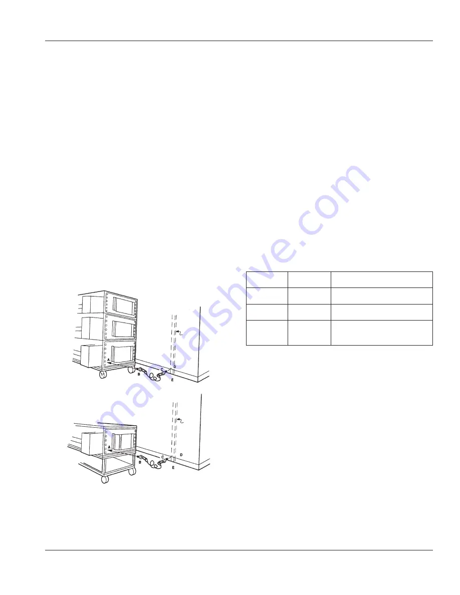
Procedure
1. Screw lifting eye end “B” of cable assembly to hole “A”.
Use 1/4" eye.
2. Screw eye bolt end “C” of cable assembly to stud in wall
“D” or floor anchor “E”.
NOTE: Installation point is the same for single, double, or
triple-stacked ovens.
Wall
Floor
Stud
Wall
Floor
Stud
Back of Single Oven
Installation
The instructions that follow are intended as a guide for
preparing for the installation of the Impinger® Conveyor
Ovens. First and foremost, each crate should be examined
before signing the Bill of Lading to report any visible
damage by the trucker in transit, and to account for the
proper number of crates.
IF THERE IS APPARENT DAMAGE:
UNITED STATES AND CANADA: Arrangements should
be made to file a claim against the carrier, as Interstate
Commerce Regulations require that the consignee initiate
a claim.
ALL SHIPMENTS TO OTHER COUNTRIES: Freight terms will
be developed and extended on an individual basis.
Proper and secure storage facilities should be arranged for
the oven(s). If necessary, protect it from outdoor or damp
conditions at all times before installation.
PACKING AND WEIGHTS
All uncrated components of the Impinger® Conveyor Oven
will pass through a 30" (762 mm) wide door. The Impinger®
Conveyor Oven consists of:
Cartons or
Crates
Weight of
Each
Dimensions of Each
1 – oven
(export)
486 lbs.
(220.5 Kilo)
43-1/2" x 63" x 24"
(1104.9 x 1600.2 x 609.6 mm)
1 – oven
(domestic)
396 lbs.
(180.0 Kilo)
42" x 59" x 23"
(1066.8 x 1498.6 x 584.2 mm)
1 – stand
(export &
domestic)
45 lbs.
(20.4 Kilo)
42" x 26" x 5"
(1066.8 x 660.4 x 127 mm)
UNCRATING
When you have all the crates unloaded, open the crates and
remove the plastic covers. Inspect at once for concealed
damage. If anything appears to be damaged, contact the
appropriate persons immediately to file a damage claim.
After completing this inspection, finish unpacking the oven
and all other components. Be sure to remove the packing
cardboard from the plenum shroud. Move all components
inside near the area where they will be assembled in the
order in which they will be assembled.


