


LINCOLN GmbH • Postfach 1263 • D-69183 Walldorf • Tel +49 (6227) 33-0 • Fax +49 (6227) 33-259 • Tx 466088
Subject to modifications
Owner Manual
Technical Description
Page 3 from 13
2.1A-28001-A94
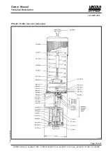
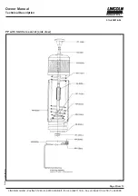
Putting into operation
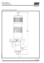
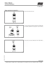
To fill the lubricant reservoir
The grease reservoir must be filled with clean lubricant via the filling
connection or the opened cover.
• be careful that no particles of dirt or other foreign matter will enter
the reservoir while the reservoir is being filled.
• refill the reservoir well in time
• keep the enviroment of the reservoir clean
During the process of venting do not stay in the vicinity of the
pump directly before the vent-plug. Risk of lubricant squirting out
of the vent hole!
All system components in the downstream system (lubricant
metering devices, tube lines, tube fittings, hoses) must at least be
designed for the maximum system pressure.
The following items must be considered:
Electrical connections
All operations on electrical equipment must be out by qualified
staff only.
Electrical connection of level controls
in accordance with terminal diagrams in Annex or with cicuit diagram
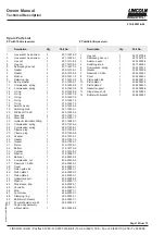
Maintenance and repair
All repair work must be executed only by authorized and quali-
fied personnel using original spare parts.
Prior to any pump repair, the following instructions must be com-
plied with:
• disconnect air supply to pump and protect it against accidental
restart.
• relieve pump and system pressure to zero bar. For this purpose
loosen the pressure connection on the pump.
• For grease pumps: The spring of the follower plate in the reservoir
is reloaded. For disassembly only use appropriate tools.
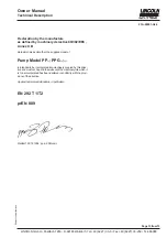
All repair work beyond the expertise of the user must be carried out
by LINCOLN qualified experts. For this purpose either the defective
pump can be returned to the Repair Department of the Walldorf
factory or an experts can be requested to execute the repair on site.
Service address:
LINCOLN GmbH Customer Service
Postfach 1263
D-69183 Walldorf
Tel +49 (6227) 33-0
Fax +49 (6227) 33-259
CAUTION


