Lincoln Electric VANTAGE 400 AU 11959 Operator'S Manual Download Page 24

When in the TOUCH START TIG mode and when a

Amptrol is connected to the 6-Pin connector the OUT-

PUT CONTROL dial is used to set the maximum cur-

rent range of the current control of the Amptrol.

The ARC CONTROL is not active in the TIG mode. To

STOP a weld, simply pull the TIG torch away from the

work. 

When the arc voltage reaches approximately 30 Volts

the arc will go out and the machine will reset the cur-

rent to the Touch Start level. 

To reinitiate the arc, retouch the tungsten to the work

and lift. Alternatively, the weld can be stopped by

releasing the Amptrol or arc start switch.

The VANTAGE® 400 (AU) can be used in a wide vari-

ety of DC TIG welding applications. In general the

‘Touch Start’ feature allows contamination free start-

ing without the use of a Hi-frequency unit. If desired,

the K930-2 TIG Module can be used with the VAN-

TAGE® 400 (AU). The settings are for reference.

VANTAGE® 400 (AU) settings when using the K930-2

TIG Module with an Amptrol or Arc Start  Switch:

•  Set the MODE Switch to the TOUCH START TIG

setting.

•  Set the "IDLER" Switch to the "AUTO" position.

•  Set the "WELDING TERMINALS" switch to the

"REMOTELY CONTROLLED" position. 

The OUTPUT CONTROL dial adjusts the full output

range for pipe welding.

The ARC CONTROL dial sets the short circuit current

(arc-force) during stick welding to adjust for a soft or

more forceful digging arc (crisp). Increasing the number

from -10(soft) to +10(crisp) increases the short circuit

current which results in a more forceful digging arc. 
Typically a forceful digging arc is preferred for root and

hot passes. A softer arc is preferred for fill and cap pass-

es where weld puddle control and deposition (“stacking”

of iron) are key to fast travel speeds. This can also

increase spatter. 
It is recommended that the ARC CONTROL be set to the

minimum number without electrode sticking. Start with

the dial set at 0.

NOte:

With the VRD switch in the “ON” position there is

no output in the DOWNHILL PIPE mode. For indicator

light operation, see table B.1.

tIG WeLDING

The TOUCH START TIG setting of the MODE switch is

for DC TIG (Tungsten Inert Gas) welding. To initiate a

weld, the OUTPUT CONTROL dial is first set to the

desired current and the tungsten is touched to the work.

During the time the tungsten is touching the work there is

very little voltage or current and, in general, no tungsten

contamination. Then, the tungsten is gently lifted off the

work in a rocking motion, which establishes the arc. 

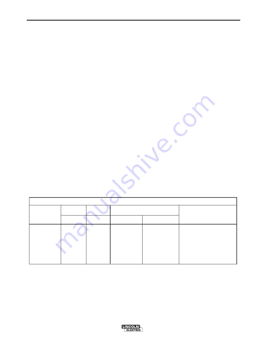
tyPICaL CURReNt RaNGes 

(1)

fOR tUNGsteN eLeCtRODes

(2)

Tungsten Electrode                DCEN (-)               DCEP (+)                 Approximate Argon Gas Flow           

TIG TORCH   

Diameter in. (mm)

Flow Rate C.F.H. ( l  /min.)

Nozzle Size (4), (5)

1%, 2% Thoriated        1%, 2% Thoriated    Aluminum

Stainless Steel

Tungsten

Tungsten

.010                   (.25)                  2-15

(3)

3-8

(2-4)      

3-8

(2-4) 

#4, #5, #6

0.020

(.50)                  5-20

(3)

5-10

(3-5)

5-10

(3-5)

0.040      

(1.0)                15-80

(3)

5-10

(3-5)

5-10

(3-5)

1/16

(1.6)                 70-150

10-20

5-10

(3-5)

9-13

(4-6)

#5, #6

3/32

(2.4)               150-250

15-30

13-17       (6-8)

11-15

(5-7)

#6, #7, #8

1/8

(3.2)

250-400

25-40

15-23      (7-11)

11-15

(5-7)

5/32

(4.0)               400-500

40-55

21-25

(10-12)

13-17

(6-8)

#8, #10

3/16

(4.8)               500-750

55-80

23-27      (11-13)

18-22

(8-10)

1/4

(6.4)

750-1000

80-125

28-32

(13-15)

23-27

(11-13)

(1) When used with argon gas.  The current ranges shown must be reduced when using argon/helium or pure helium shielding gases.

(2) Tungsten electrodes are classified as follows by the American Welding Society (AWS):

Pure

EWP

1% Thoriated

EWTh-1

2% Thoriated

EWTh-2

Though not yet recognized by the AWS, Ceriated Tungsten is now widely accepted as a substitute for 2% Thoriated Tungsten in AC and DC applications.

(3)  DCEP is not commonly used in these sizes.

(4)  TIG torch nozzle "sizes" are in multiples of 1/16ths of an inch:

# 4 = 1/4 in.

(6 mm)

# 5 = 5/16 in.

(8 mm)

# 6 = 3/8 in.

(10 mm)

# 7 = 7/16 in.

(11 mm)

# 8 = _ in.

(12.5 mm)

#10 = 5/8 in.

(16 mm)

(5) TIG torch nozzles are typically made from alumina ceramic.  Special applications may require lava nozzles, which are less prone to breakage, but cannot withstand high temperatures

and high duty cycles.

B-6

OPeRatION

B-6

taBLe B.3

VaNtaGe® 400 (aU)

Summary of Contents for VANTAGE 400 AU 11959

Page 1: ...nes having Code Numbers 11959 12307 Need Help Call 1 888 935 3877 to talk to a Service Representative Hours of Operation 8 00 AM to 6 00 PM ET Mon thru Fri After hours Use Ask the Experts at lincolnel...

Page 2: ...he general area IN A LARGE ROOM OR OUTDOORS natural ventilation may be adequate if you keep your head out of the fumes See below USE NATURAL DRAFTS or fans to keep the fumes away from your face If you...

Page 3: ...y guards covers and devices in position and in good repair Keep hands hair clothing and tools away from V belts gears fans and all other moving parts when starting operating or repairing equipment 1 e...

Page 4: ...ANSI Z87 I standards 4 b Use suitable clothing made from durable flame resistant material to protect your skin and that of your helpers from the arc rays 4 c Protect other nearby personnel with suita...

Page 5: ...lifting chains crane cables or other alternate circuits This can create fire hazards or overheat lifting chains or cables until they fail 6 h Also see item 1 c 6 I Read and follow NFPA 51B Standard fo...

Page 6: ...ponsibility of the user of the welding equipment to resolve the situation with the technical assistance of the manufacturer In some cases this remedial action may be as simple as earthing grounding th...

Page 7: ...ommendations Welding Cables The welding cables should be kept as short as possible and should be positioned close together running at or close to floor level Equipotential Bonding Bonding of all metal...

Page 8: ...ly important when identifying the correct replacement parts On Line Product Registration Register your machine with Lincoln Electric either via fax or over the Internet For faxing Complete the form on...

Page 9: ...8 ________________________________________________________________________________ Operation section B Safety Precautions B 1 General Description B 1 For Auxiliary Power B 1 Engine Operation B 1 Add...

Page 10: ...g Optional Spark Arrestor D 5 Welder Generator Maintenance D 6 Storage D 6 Cleaning D 6 Brush Removal and Replacement D 6 ________________________________________________________________________ troub...

Page 11: ...ssure Mechanical Fuel Pump Auto air bleed Mechanical with Full Flow Filter EPA Tier IV Interim system Electric shutoff solenoid Indirect fuel injector aIR CLeaNeR eNGINe IDLeR MUffLeR eNGINe PROteCtIO...

Page 12: ...ptacles Residual Current Device RCD Circuit Breakers Thermal Magnetic Other Circuit Breakers 400V 3 Ph x 1 230V 1 Ph x 2 14 Pin Connector 6 Pin Connector 4 pole 40Amp 30mA trip current 3 Phase 20 Amp...

Page 13: ...od electrical con nections also limits the possibility of other safety issues such as heat generated damage burns and fires The machine is shipped with the VRD switch in the On position To turn it On...

Page 14: ...weight of Lincoln equipment and likely additional attachments 2 Proper support of and attachment to the base of the welding equipment so there will be no undue stress to the framework 3 Proper placem...

Page 15: ...ighways MUffLeR OUtLet PIPe Using the clamp provided secure the outlet pipe to the outlet tube with the pipe positioned such that it will direct the exhaust in the desired direction Tighten using a 9...

Page 16: ...ding stud marked with the symbol is provided on the front of the welder WeLDING teRMINaLs The VANTAGE 400 AU is equipped with a toggle switch for selecting hot welding terminal when in the WELD TERMIN...

Page 17: ...the high idle speed the wire will begin to feed and the welding process started When welding is stopped the engine will revert to low idle speed after approximately 12 seconds unless welding is resum...

Page 18: ...ng clip at the end of the lead This is a control lead to supply current to the wire feeder motor it does not carry welding current 4 Set the MODE switch to the CV WIRE position 5 Set the WELD TERMINAL...

Page 19: ...he desired operating mode Full power is available regardless of the welding control settings providing no welding current is being drawn eNGINe OPeRatION Before Starting the Engine Be sure the machine...

Page 20: ...connected to the 14 Pin Connector the auto sensing circuit automatically makes OUTPUT CONTROL inactive and the wire feeder voltage control active Otherwise the OUTPUT CONTROL is used to preset the vo...

Page 21: ...uipment Includes auto sensing remote control circuit 9 WeLD teRMINaLs CONtROL sWItCH In the WELD TERMINALS ON position the output is electrically hot all the time In the REMOTELY CONTROLLED position t...

Page 22: ...INe HOUR MeteR Displays the total time that the engine has been running This meter is useful for scheduling prescribed maintenance 18 eNGINe PROteCtION LIGHt A warning indi cator light for Low Oil Pre...

Page 23: ...lve is located on the fuel pre filter CaUtION The ARC CONTROL dial sets the short circuit current arc force during stick welding to adjust for a soft or crisp arc Increasing the number from 10 soft to...

Page 24: ...With the VRD switch in the ON position there is no output in the DOWNHILL PIPE mode For indicator light operation see table B 1 tIG WeLDING The TOUCH START TIG setting of the MODE switch is for DC TIG...

Page 25: ...s is to receive a low voltage welding process There is no difference in operation with the VRD On or Off for this mode For indicator light oper ation see table B 1 WIRe WeLDING CV Connect a wire feede...

Page 26: ...ty KP1697 5 64 Drive Roll Kit Includes 2 polished U groove drive rolls outer wire guide and inner wire guide for solid core wire Used on LN 25 Pro KP1697 068 Drive Roll Kit Includes 2 polished U groov...

Page 27: ...All nuts and bolts for tightness Electrical systems Valve clearances Tighten cylinder head Renew the engine breather Air filter element Air filter earlier check may be required Alternator drive belt A...

Page 28: ...he oil container to be sure it includes the letters indicated Note An S grade oil must not be used in a diesel engine or damage may result It IS permissible to use an oil that meets S and C grade serv...

Page 29: ...itself and distribute the sealing pressure evenly To complete a tight seal apply pressure by hand at the outer rim of the filter not the flexible center Avoid pushing on the center of the urethane end...

Page 30: ...signs of deterioration are found tIGHteNING tHe faN BeLt If the fan belt is loose the engine can overheat and the battery lose its charge Check tightness by press ing on the belt midway between the p...

Page 31: ...o the machine can result if operated at speeds above maximum CLeaNING tHe BatteRy Keep the battery clean by wiping it with a damp cloth when dirty If the terminals appear corroded discon nect the batt...

Page 32: ...rings to wear and darken slightly Inspect the brushes when a generator over haul is necessary Do not attempt to polish slip rings while the engine is running service and Repair should only be perform...

Page 33: ...LE CAUSE lists the obvious external possibilities that may contribute to the machine symptom Step 3 RECOMMENDED COURSE OF ACTION This column provides a course of action for the Possible Cause generall...

Page 34: ...vertical position of handle 2 Fuel Filters dirty clogged Check and replace main filter element and or Inline Fuel Filter 3 Out of fuel Fill tank and bleed fuel system 4 High coolant temperature or low...

Page 35: ...sides of base and exhaust end case back 1 Dirty fuel or air filters Inspect and clean replace filters as needed Inspect and clean replace filters as needed 2 Water in fuel If water found in tank Empty...

Page 36: ...kage or broken spring 2 Faulty PC board Control or Idler 1 Fuel filter clogged Replace 2 Air filter clogged clean or replace 3 High idle setting incorrect check and adjust if required 4 Valves out of...

Page 37: ...Weld Terminals On position when welding without control cable 3 Faulty PC board or welder alterna tor 1 Poor remote control cable connec tion to 6 pin or 14 pin connector Check connections 2 Faulty re...

Page 38: ...re the electrode wire gas voltage current etc is correct for the process being used 3 Check for loose or faulty connec tions at the weld output terminals and welding cable connections 4 The welding ca...

Page 39: ...f 1 DIaGRaMs f 1 VaNtaGe 400 aU...

Page 40: ...f 2 DIaGRaMs f 2 VaNtaGe 400 aU...

Page 41: ...f 3 DIaGRaMs f 3 VaNtaGe 400 aU...

Page 42: ...f 4 DIaGRaMs f 4 VaNtaGe 400 aU...

Page 43: ...r reference only It may not be accurate for all machines covered by this manual the specific diagram for a particular code is included with the machine If the diagram is illegible write to the service...

Page 44: ...5 50 1409 7 2 25 57 2 5 75 146 0 35 94 913 0 24 00 609 6 39 81 20 60 523 3 28 95 735 3 36 06 915 9 28 13 714 5 60 00 1524 0 16 25 412 8 N A N A CENTER OF GRAVITY WITH OIL IN ENGINE COOLANT IN RADIATOR...

Page 45: ...parts or electrode with skin or wet clothing l Insulate yourself from work and ground l No toque las partes o los electrodos bajo carga con la piel o ropa moja da l Aislese del trabajo y de la tierra...

Page 46: ...d Entl ftung des Arbeitsplatzes l Mantenha seu rosto da fuma a l Use ventila o e exhaust o para remover fumo da zona respirat ria l Turn power off before servicing l Desconectar el cable de ali mentac...

Page 47: ...tomer s particular purpose with respect to such information or advice As a matter of practical consideration we also cannot assume any responsibility for updating or correcting any such information or...

Reviews: