Lincoln Electric Tandem MIG AD1202-1 Specification Sheet Download Page 10

Tandem MIG 

T

h

e


f

u

t

u

r

e


o

f


w

e

l

d

i

n

g


i

s


h

e

r

e

.

®

APPLICATION

10/16

High-Speed and High-Deposition Welding

W A V E F O R M   C O N T R O L   T E C H N O L O G Y

T M

Using Tandem MIG

Understanding Operating Variables

The general rules governing operating variables for single wire GMAW arc welding also apply to Tandem MIG
welding. However there are additional considerations that must be kept in mind when welding with multiple arcs.
Since the two arcs will interact, the type of power fed to each arc, the wire feed speed ratio between lead and trail,
the arc lengths, the wire positioning, and torch angles must be set correctly. The enclosed procedures are starting
points and may need to be altered based on specific application conditions. Adherence to the following guidelines
will assist in achieving the maximum potential of the process.

Lead Arc

The lead arc creates the majority of the penetration and should represent the majority of the total deposition 
rate of the process. When using like diameter electrodes for the lead and the trail, the lead should represent
approximately 60% of the total wire feed. In the case where a larger wire diameter is used as a lead (for added
penetration) the lead should represent approximately 60% or more of the total deposition. The lead arc can be
operated in a Tandem pulse, CV or Power mode. Pulse is recommended for the high deposition procedures.
Power mode or CV may be used for greater lead arc stability in high travel speed applications.

Trail Arc

The trail arc is used to cool the weld pool and control the bead contour and is always operated in the Tandem
pulse mode. The trail should be kept directly in line with the lead arc and focused on the center of the weld pool.
The trail wire should represent approximately 40 % of the process deposition rate. The Tandem MIG trail pulse
waveforms are designed to operate at low voltages to limit arc interaction and minimize arc blow.

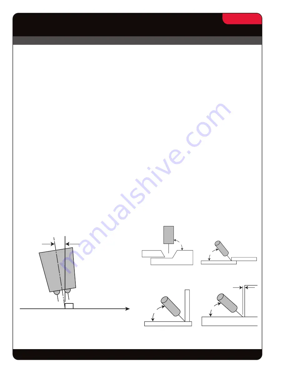
Torch Positioning

Torch positioning may be altered for specific applications. A 5-degree push angle is recommended for high 
deposition welding. A (0-5)-degree angle is recommended for high speed welding.

Push Angle

Travel

Directionl

A 5-degree push angle

is recommended

Flat Welds

(Beveled Butt, Fillets, Laps

Horizontal Welds

Lap

Horizontal Welds

Small Fillet

Horizontal Welds

Large Fillet

Travel Angle

Joint Angle

90°

65°

45°

40°

Push Angle

Travel

Direction

1/2” Wire Dia.

Summary of Contents for Tandem MIG AD1202-1

Page 1: ...e wire GMAW processes INCREASED TRAVEL SPEEDS The combined contribution of two separate welding arcs in one weld pool provides the control to overcome the lack of follow tendencies of single arc proce...

Page 2: ...would be The two welding arcs that are generated in the Tandem MIG process are electrically isolated from one another and are controlled independently The welding arcs work together generally separate...

Page 3: ...ol follow speed The trail arc should be kept directly in line with the lead arc and focused on the center of the weld pool The trail wire melting rate typically represents approximately 40 of the proc...

Page 4: ...rage systems trash hauling containers and similar components are welded with 2 035 diameter electrodes to produce welds at travel speeds ranging from 80 100 ipm Larger 4 6 mm fillet welds common to st...

Page 5: ...e and multi pass beveled butt welds used in industries fabricating ship hulls earth moving equipment structural platforms pressure vessels beams and similar heavy plate weldments are performed at depo...

Page 6: ...require the use of larger wire diameters or higher wire feed speeds Both choices will cause an increase in current draw The added current draw creates added penetration that must be managed With a sin...

Page 7: ...ld porosity The elevated welding currents create weld pool turbulence that can cause root porosity or porosity just below the surface of the weld bead Solution Tandem MIG The two wire electrode config...

Page 8: ...rocess the two smaller diameter electrodes produce a lower heat input and improved weld pool control when compared to a larger single electrode process attempting to perform similar welds When compare...

Page 9: ...T R O L T E C H N O L O G Y T M Comparing High Deposition Tandem MIG To Single Wire GMAW Process Deposition Rate Comparison 40 20 30 Single Wire GMAW Lbs Hr Tandem MIG 1 4 Horizontal Fillet 10 Weld Me...

Page 10: ...the total wire feed In the case where a larger wire diameter is used as a lead for added penetration the lead should represent approximately 60 or more of the total deposition The lead arc can be ope...

Page 11: ...e added penetration but may produce added spatter The lower CO2 will produce less spatter 3 95 5 Ar O2 is recommended for high speed welding of thin gage material under 3mm The mixture will provide im...

Page 12: ...ceNet Communication Cables drops 20 in S23383 4 S23383 4 2 F DeviceNet Communication Cables trunk line 19 5 ft S23383 2 S23383 2 1 G Communication cables Power source to wire feeders 25 ft K1785 25 K1...

Page 13: ...4 0 25 14 14 L 4 0 25 14 14 2 F Fanuc RJ3iB robot and controller Arc tool software 6 4 or above 100 or 120 Series RJ3iB Controller 100 or 120 Series RJ3iB Controller 1 Dual channel DeviceNet board S23...

Page 14: ...tor driving the feeder mechanism in a sheet metal frame The logic for controlling the wire feeder resides in a PC board inside the robotic power source Tandem MIG High Speed and High Deposition Weldin...

Page 15: ...num and nickel alloys Custom control of the arc for each wire type and size provide consistent welds time after time These Power Waves are designed to be part of a modular multi process welding system...

Page 16: ...f arc welding processes Advancements in power electronics digital communications and Waveform Control Technology are the foundation for many of the improvements NEXTWELD brings you a series of Process...

Reviews: