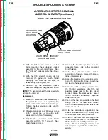
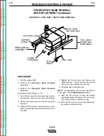
background image

Retur

n to Section TOC

Retur

n to Section TOC

Retur

n to Section TOC

Retur

n to Section TOC

Retur

n to Master TOC

Retur

n to Master TOC

Retur

n to Master TOC

Retur

n to Master TOC

TROUBLESHOOTING & REPAIR

F-27

F-27

SA-250

FLASHING THE FIELDS

(continued)

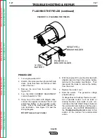
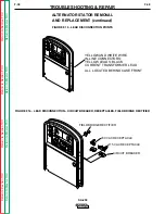
FIGURE F.10 - FLASHING THE FIELDS

NEGATIVE (-)
BRUSH HOLDER

POSITIVE (+)
BRUSH HOLDER

12 VOLT
BATTERY

_

+

PROCEDURE

1.

Turn engine welder OFF.

2.

Unlatch, lift and secure the right and left side
doors.  Note that there are latches at both
ends of the door.

3.

Remove the cover from the exciter.  See
Figure F.10.

4.

Turn the FINE CURRENT ADJUSTMENT
control (rheostat) to “100.”

5.

Using one of the leads with alligator clips,
connect the negative terminal of the 12-volt
automotive battery to the negative brush-
holder.  This is the brushholder nearest the
rotor lamination.  See Figure F.10 and the
Wiring Diagram.  

DO NOT remove brush holder.

6.

With the engine OFF, use the other lead with
alligator clips and touch the positive battery
terminal to the positive brushholder.  Then
disconnect the leads to remove the battery
from the circuit.  

7.

Replace the exciter cover.  

8.  Start the welder.  The generator voltage

should build up.  

If voltage does not build up, there are a num-
ber of possible causes, such as loose or
missing brushes, open leads or poor con-
nections at the field diode bridge or between
the exciter alternator brushes and the gener-
ator brushes.  See OUTPUT PROBLEMS in
the 

Troubleshooting Guide located in this

section of the manual for recommended
action. 

Summary of Contents for SHIELD-ARC SA-250

Page 1: ...ore you act and be careful SERVICE MANUAL For use with machine code numbers 10073 or 10073CV SHIELD ARC SA 250 Diesel Engine Driven DC Arc Welding Power Source TM Return to Master TOC Return to Master TOC Return to Master TOC Return to Master TOC View Safety Info View Safety Info View Safety Info View Safety Info RETURN TO MAIN INDEX Sales and Service through Subsidiaries and Distributors Worldwid...

Page 2: ...CTOR BEFORE OPERATING Read and understand the following safety highlights For additional safety information it is strongly recommended that you purchase a copy of Safety in Welding Cutting ANSI Standard Z49 1 from the American Welding Society P O Box 351040 Miami Florida 33135 or CSA Standard W117 2 1974 A Free copy of Arc Welding Safety booklet E205 is available from the Lincoln Electric Company ...

Page 3: ...ctrode holder work clamp welding cable and welding machine in good safe operating condition Replace damaged insulation 3 g Never dip the electrode in water for cooling 3 h Never simultaneously touch electrically hot parts of electrode holders connected to two welders because voltage between the two can be the total of the open circuit voltage of both welders 3 i When working above floor level use ...

Page 4: ... a fire Remember that welding sparks and hot materials from welding can easily go through small cracks and openings to adjacent areas Avoid welding near hydraulic lines Have a fire extinguisher readily available 6 b Where compressed gases are to be used at the job site special precautions should be used to prevent hazardous situations Refer to Safety in Welding and Cutting ANSI Standard Z49 1 and ...

Page 5: ...e laitier en fusion sont émises de l arc de soudage Se protéger avec des vêtements de protection libres de l huile tels que les gants en cuir chemise épaisse pan talons sans revers et chaussures montantes 5 Toujours porter des lunettes de sécurité dans la zone de soudage Utiliser des lunettes avec écrans lateraux dans les zones où l on pique le laitier 6 Eloigner les matériaux inflammables ou les ...

Page 6: ...iption B 2 Recommended Applications B 3 Operational Features and Controls B 3 Design Features B 3 Welding Capability B 4 Limitations B 4 Controls and Settings B 5 Engine Operation B 8 Welding Operation B 10 Auxiliary Power B 12 Accessories Section C Maintenance Section D Safety Precautions D 2 Routine and Periodic Maintenance D 2 Major Component Locations D 13 Theory of Operation Section E Trouble...

Page 7: ...peration Engine Service A 4 Oil A 4 Fuel A 4 Battery Connections A 4 Cooling System A 5 Muffler A 5 Exhaust Spark Arrester A 5 Trailer A 5 Electrical Output Connections A 6 Welding Cable Connections A 6 Cable Installation Polarity Control and Cable Sizes A 6 Machine Grounding A 7 Auxiliary Power Receptacles Plugs and Hand held Equipment A 7 Circuit Breakers A 7 Return to Master TOC Return to Maste...

Page 8: ... 1350 RPM Water coolant 10 qt Low idle 9 5 liters RATED OUTPUT WELDER Duty Cycle Amps Volts at Rated Amperes 100 Duty Cycle 200 DC Constant Current 40V 60 Duty Cycle 250 DC Constant Current 40V 1 35 Duty Cycle 325 DC Constant Current 33V OUTPUT WELDER AND GENERATOR Welding Ranges Max Open Circuit Voltage Auxiliary Power 40 325 Amps DC 98 5 3 0 kVA of 115 230 V 60Hz Power 26 Amps 115 V 2 13 Amps 23...

Page 9: ... Whenever you use the SA 250 be sure that clean cooling air can flow through the machine s diesel engine and the generator Avoid dusty dirty areas Also keep the machine away from heat sources Do not place the back end of the generator anywhere near hot engine exhaust from another machine And of course make sure that engine exhaust is ventilated to an open outside area The SA 250 may be used outdoo...

Page 10: ...ly to release pressure Do not overfill the fuel tank Wipe up spilled fuel and allow the fumes to clear before starting the engine Keep sparks and flame away from the fuel tank OIL The SA 250 is shipped with the engine filled with SAE 10W 30 oil This should be fine for most ambient operating temperature conditions See the engine operation manual for spe cific recommendations CHECK THE OIL LEVEL BEF...

Page 11: ...am age or performance loss Contact the engine manu facturer for specific recommendations TRAILER If you use a non Lincoln trailer you must assume responsibility that the method of attachment and usage does not result in a safety hazard nor damage the welding equipment Some of the factors to be consid ered are as follows 1 Design capacity of the trailer vs the weight of the Lincoln equipment and li...

Page 12: ...considerable distance from the welder be sure you use ample size welding cables Table A 1 lists recommended cable sizes and lengths for rated current and duty cycle Length refers to the distance from the welder to the work and back to the welder Cable diameters are increased for long cable lengths to reduce voltage drops Lincoln Electric offers a welding accessory kit with the properly specified w...

Page 13: ...rtz With the 3 0 kVA 115 230V AC auxiliary power one 115V duplex and one 230V duplex grounding type receptacle are provided The circuit is protected with circuit breakers The rating of 3 0 kVA permits a maximum continuous current of 13 amps to be drawn from the 230 volt duplex receptacle Or a total of 26 amps can be drawn from the 115 volt duplex receptacle The 115 volt duplex receptacle has a con...

Page 14: ...NOTES A 8 A 8 SA 250 Return to Section TOC Return to Section TOC Return to Section TOC Return to Section TOC Return to Master TOC Return to Master TOC Return to Master TOC Return to Master TOC ...

Page 15: ...ontrols and Settings B 5 Welder Generator Controls B 5 Control of Welding Current B 6 Diesel Engine Controls B 7 Engine Operation B 8 Before Starting the Engine B 8 Starting the Engine B 8 Stopping the Engine B 9 Cold Weather Starting B 9 Break in Period B 9 Welding Operation B 10 SA 250 DC Constant Current Stick or TIG Welding B 10 SA 250 DC Wire Feed Welding Constant Voltage B 11 Auxiliary Power...

Page 16: ...ted areas or vent exhaust to the outside Do not stack anything on or near the engine MOVING PARTS can injure Do not operate this equipment with any of its doors open or guards off Stop the engine before servicing it Keep away from moving parts Only qualified personnel should install use or ser vice this equipment GENERAL DESCRIPTION The SA 250 is a heavy duty engine driven DC arc welding power sou...

Page 17: ... speed for welding or auxiliary power applications See Engine Operation in the Operation section of this manual for details about starting run ning stopping and breaking in the diesel engine DESIGN FEATURES Constant current DC Stick welding SMAW process capability with output range from 40 325 DC amps Constant current DC TIG Welding with output across the entire range of settings Work and Electrod...

Page 18: ...ny processes besides those that are normally performed using DC stick welding SMAW and DC TIG welding Specific limitations on using the SA 250 for these processes are described in the Welding Operation section of this manual Constant voltage welding is available with the optional Wire Feed Module OPERATION B 4 B 4 SA 250 Return to Section TOC Return to Section TOC Return to Section TOC Return to S...

Page 19: ...ge See Control of Welding Current for more information 3 230 VOLT DUPLEX RECEPTACLE Connection point for supplying 230 volt power to operate one or two electrical devices 4 115 VOLT DUPLEX RECEPTACLE Connection point for supplying 115 volt power to operate one or two electrical devices 5 WELD OUTPUT TERMINAL WITH FLANGE NUT Provides the connection point for either the electrode holder or the work ...

Page 20: ...ft arc set the CURRENT RANGE SELECTOR to the 190 120 posi tion and then adjust the FINE CURRENT ADJUST MENT for 175 amps When a forceful digging arc is required usually for vertical and overhead welding use a higher CURRENT RANGE SELECTOR setting and lower open circuit voltage For example to obtain 175 amps and a force ful arc set the CURRENT RANGE SELECTOR to 240 160 position and the FINE CURRENT...

Page 21: ...between 10 F 12 C and freezing NOTE If you press either START pushbutton when the engine is running you may damage the engine flywheel gear or starter motor 5 ENGINE HOUR METER Records engine running time Use the meter to determine when to perform required maintenance 6 OIL PRESSURE GAUGE Indicates engine oil pressure If no oil pressure shows on the gauge within 30 seconds after startup the engine...

Page 22: ... igniting Do not spill fuel when filling tank If fuel is spilled wipe it up and do not start engine until fumes have been elimi nated 1 Remove the fuel tank cap 2 Fill the tank to allow approximately 1 4 inch 5 mm of tank space for fuel expansion DO NOT FILL THE TANK TO THE POINT OF OVERFLOW 3 Replace the fuel tank cap and tighten securely NOTE USE DIESEL FUEL ONLY Purchase diesel fuel in quantiti...

Page 23: ...structions on the nameplate and in the engine manual shipped with the welder With a fully charged battery and the proper weight oil the engine should start satisfactorily even when the air temperature is down to about 0o F 18 C If the engine is frequently started below 10o F 12 C you may want to remove the Thermostart and install the optional ether starter kit Installation and operating instructio...

Page 24: ...red welding current 8 Set the FINE CURRENT ADJUSTMENT to the set ting that gives the best arc characteristics for the range selected See Control of Welding Current in this section of the manual 9 Strike an arc and begin welding After you finish welding 1 Stop the engine See Engine Operation in this section of the manual 2 Allow the electrode and work to cool completely 3 Remove the work clamp from...

Page 25: ...size and wire feed speed See Table B 1 for recommended settings 6 Set the VOLTAGE ADJUSTMENT to the setting that gives the best arc characteristics for the range selected 7 Pull the gun trigger and begin welding OPERATION B 11 B 11 SA 250 Return to Section TOC Return to Section TOC Return to Section TOC Return to Section TOC Return to Master TOC Return to Master TOC Return to Master TOC Return to ...

Page 26: ...ot exceed 3 0 kVA An optional power plug kit is available When this kit is specified the customer is supplied with a plug for each receptacle See the Accessories section of this man ual An optional GFCI 115 volt receptacle kit is also avail able Note that the use of this GFCI kit reduces avail able current to a total of 20 Amps of available 115 volt power See the Accessories section of this manual...

Page 27: ...4 Connection of the LN 7 using K867 Universal Adapter C 4 Connection of the LN 7 using K584 Input Cable Assembly C 5 Connection of the LN 25 using K867 Universal Adapter C 6 Connection of the LN 25 Across the Arc C 7 Connection of the K488 SG Control Module and K487 Magnum Spool Gun C 8 Section C 1 Section C 1 SA 250 Return to Master TOC Return to Master TOC Return to Master TOC Return to Master T...

Page 28: ...s conditions Do not use a welder to thaw pipes before reviewing Lincoln Bulletin E695 1 dated October 1987 or later Wire Feed Module K623 1 Provides constant voltage output for semiautomatic welding Includes remote for CV mode and internal Cold Tip Contactor Accessory Kit K703 Includes the following Electrode cable Work cable Headshield Work clamp Insulated electrode holder Remote Control K924 1 I...

Page 29: ...EMIAUTOMATIC WELDING ACCESSORIES LN 25 Wire Feeder This portable wire feeder is capa ble of CC CV wire feed welding LN 7 Wire Feeder Semiautomatic constant speed wire feeder For CV operation only NOTE Gas shielded welding requires a Magnum Gun Gasless welding requires an Innershield Gun Magnum Spool Gun K487 25 A lightweight semi automatic wire feeder for aluminum welding with argon gas Has built ...

Page 30: ...the governor setting or overriding the throttle linkage will cause an increase in the AC auxiliary voltage If this voltage goes over 140 volts wire feeder control circuits may be damaged The engine governor set ting is preset at the factory do not adjust above RPM specifications listed in this manual 6 Adjust wire feed speed at the LN 7 NOTE For remote control a K775 remote control is required See...

Page 31: ...Any increase of the high idle engine RPM by changing the governor setting or overriding the throttle linkage will cause an increase in the AC auxiliary voltage If this voltage goes over 140 volts wire feeder control circuits may be damaged The engine governor set ting is preset at the factory do not adjust above RPM specifications listed in this manual 6 Adjust wire feed speed at the LN 7 NOTE For...

Page 32: ...ped with the K431 1 remote output control kit 5 Place the IDLER switch in the HIGH position Any increase of the high idle engine RPM by changing the governor setting or overriding the throttle linkage will cause an increase in the AC auxiliary voltage If this voltage goes over 140 volts wire feeder control circuits may be damaged The engine governor set ting is preset at the factory do not adjust ...

Page 33: ...he K444 2 remote control cable to the 14 pin amphenol on the wire feed module 4 Attach the single lead from the LN 25 control box to the work using the spring clip on the end of the lead This is only a control lead it carries no welding current 5 Place the IDLER switch in the HIGH position 6 Adjust wire feed speed and voltage at the LN 25 ACCESSORIES C 7 C 7 SA 250 Return to Section TOC Return to ...

Page 34: ...the SA 250 6 Place the IDLER switch on the SA 250 in the HIGH position Any increase of the high idle engine RPM by changing the governor setting or overriding the throttle linkage will cause an increase in the AC auxiliary voltage If this voltage goes over 140 volts wire feeder control circuits may be damaged The engine governor set ting is preset at the factory do not adjust above RPM specificati...

Page 35: ... Eliminate Air From the Fuel System D 5 Cooling System D 7 Tightening the Fan Belt D 8 Engine Maintenance Schedule D 9 Battery Maintenance D 10 Cleaning the Battery D 10 Checking Specific Gravity D 10 Checking Electrolyte Level D 10 Charging the Battery D 10 Welder Generator Maintenance D 11 Storage D 11 Cleaning D 11 Nameplates D 11 Brush Removal and Replacement D 11 Commutator and Brushes D 11 B...

Page 36: ...chever come first More fre quent service may be required depending on your spe cific application and operating conditions OIL Check the oil level after every 8 hours of operation or daily BE SURE TO MAINTAIN THE OIL LEVEL Change the oil the first time between 25 and 50 hours of operation Then under normal operating conditions change the oil as specified in Table D 1 If the engine is operated under...

Page 37: ...er finger tight until the gasket is evenly seated Then turn it down another 1 2 turn Do not overtighten the new filter 5 Refill the engine with the proper amount and type of oil as described in the Change the Oil section above Start the engine and check for leaks around the filter element Correct any leaks usu ally by retightening the filter but only enough to stop leaks before placing the SA 250 ...

Page 38: ...n the filter head With the assembly in this position engage and tighten the setscrew 8 Bleed the air from the fuel system See How to Eliminate Air from the Fuel System Order Perkins fuel filter 26560017 or 26561117 from your local Perkins Service Center AIR CLEANER The Perkins diesel engine is equipped with a dry type air filter Inspect the air cleaner daily more often in dusty conditions Never ap...

Page 39: ...il fuel free from air comes from the filter vent point Tighten the banjo connection bolt If the drive cam of the fuel lift pump is at the point of maximum cam lift it will not be possible to operate the priming lever In this situation the crankshaft must be turned one revolution 3 See Figure D 3 Where the fuel filter is fitted lower than the fuel injection pump loosen the inlet con nection at the ...

Page 40: ...tted ensure that it is in the run position 2 Operate the starter motor until the engine starts If the system or a component in the system has been drained 1 Turn the start key to the R position If a manual stop control is fitted ensure that it is in the run position 2 Operate the lever of the fuel lift pump slowly for approximately two minutes If the drive cam of the fuel lift pump is at the point...

Page 41: ...ler cap 3 Remove the drain plug from the side of the cylinder block in order to drain the engine Ensure that the drain hole is not restricted See Figure D 5 4 Open the radiator drain cock at the bottom of the radiator in order to drain the radiator 5 If necessary flush the system with clean water 6 Fit the engine drain plug and the radiator drain cock 7 Fill the cooling system at the radiator fill...

Page 42: ...e alternator 1 and the adjustment link fasteners 2 2 Change the position of the alternator to give the cor rect tension Tighten the pivot fasteners of the alter nator and the adjustment link fasteners 3 Check the belt tension again to ensure that it is still correct If a new belt is fitted the belt tension must be checked again after the first 25 hours of operation MAINTENANCE D 8 D 8 SA 250 Retur...

Page 43: ... air cleaner for dirty loose or damaged parts Check air intake and cooling areas clean as necessary Inspect fuel filter Drain any accumulated water from water separator First 25 50 Hours Change engine oil Change oil filter Check fan belt Check coolant Every 200 250 Check drive belts Hours Check fuel lines and clamps Check coolant Check air filter Change oil Change oil filter Check battery electrol...

Page 44: ...y can lead to more rapid discharge and early battery failure CHECKING SPECIFIC GRAVITY Check each battery cell with a hydrometer A fully charged battery will have a specific gravity of 1 260 Charge the battery if the reading is below 1 215 NOTE Correct the specific gravity reading by adding four gravity points 0 004 for every five degrees the electrolyte temperature is above 80 degrees F 27 degree...

Page 45: ...personnel seat these brushes by lightly stoning the commutator as the armature rotates at full speed until contact is made across the full face of the brushes After stoning blow out the dust with low pressure air Uncovered rotating equipment can be dangerous Use care so your hands hair clothing or tools do not catch in the rotating parts Protect yourself from particles that may be thrown out by th...

Page 46: ...enoid plunger with the vent hole on the lower side 3 Proper operation of the idler requires good ground ing of the printed circuit board through its mount ing reed switch and battery 4 If desired the welder can be used without auto matic idling by setting the Idler Control switch to the High Idle position MAINTENANCE D 12 D 12 SA 250 Return to Section TOC Return to Section TOC Return to Section TO...

Page 47: ...NANCE D 13 D 13 SA 250 FIGURE D 5 MAJOR COMPONENT LOCATIONS SA250 11 1 RIGHT CASE SIDE DOOR 2 BASE WITH BATTERY 3 ALTERNATOR BRUSHES 4 ALTERNATOR 5 GENERATOR 6 GENERATOR BRUSHES 7 OUTPUT TERMINALS 8 FUEL TANK 9 CASE FRONT WITH CONTROL PANEL 10 LEFT CASE SIDE 11 CASE TOP 12 CASE BACK WITH RADIATOR 13 COOLING FAN 14 AIR CLEANER 15 IDLER CONTROL 7 4 8 11 9 10 12 13 14 15 6 5 3 1 2 ...

Page 48: ...NOTES D 14 D 14 SA 250 Return to Section TOC Return to Section TOC Return to Section TOC Return to Section TOC Return to Master TOC Return to Master TOC Return to Master TOC Return to Master TOC ...

Page 49: ...dler Circuit E 4 DC Generator Machines E 5 TABLE OF CONTENTS THEORY OF OPERATION SECTION NEGATIVE OUTPUT TERMINAL POSITIVE OUTPUT TERMINAL 115 230VAC RECEPTACLES CURRENT TRANSFORMER FIELD RECTIFIER FLASHING RESIDUAL MAGNETISM ALTERNATOR STATOR ROTOR SLIP RINGS ARMATURE SHAFT GENERATOR ARMATURE BRUSHES COMMUTATOR GENERATOR FRAME SERIES COILS INTERPOLE COILS SHUNT WINDINGS GENERATOR FIELD CONTROL FI...

Page 50: ...itors the oil pressure switch and the coolant tempera ture sensor If either sensor faults the protection relay deactivates the fuel injection pump and the engine shuts down The engine alternator supplies charging current for the battery circuit THEORY OF OPERATION E 2 E 2 SA 250 FIGURE E 2 BATTERY STARTER ENGINE ALTERNATOR AND PROTECTION CIRCUITS NOTE Unshaded areas of Block Logic Diagram are the ...

Page 51: ...5VAC and 230VAC of auxiliary power to the appropriate receptacles The other 115VAC isolated winding is rectified to a DC voltage and is used to supply field feedback voltage to the rotor It also through the generator field rheostat control sup plies voltage to the field shunt windings in the main generator frame THEORY OF OPERATION E 3 E 3 SA 250 NOTE Unshaded areas of Block Logic Diagram are the ...

Page 52: ...oils and selector switch are connected in series with the negative output terminal FINE CURRENT ADJUSTMENT The field rheostat control functions as a fine output cur rent adjustment by controlling the current through the shunt windings In this way it controls the amount of magnetism created in the field shunt windings Open circuit weld voltage can also be controlled by the field rheostat control EN...

Page 53: ...posite points on the rotating shaft with the conductors parallel to the shaft The armature assembly is normally turned at a constant speed by a source of mechanical power con nected to the shaft Rotation of the armature through the magnetic field produced by the stationary field winding induces a coil voltage in the armature winding The voltage induced in an individual armature coil is an alternat...

Page 54: ...NOTES E 6 E 6 SA 250 Return to Section TOC Return to Section TOC Return to Section TOC Return to Section TOC Return to Master TOC Return to Master TOC Return to Master TOC Return to Master TOC ...

Page 55: ... Solenoid Test F 20 Engine Throttle Adjustment Test F 22 Flashing the Fields F 26 Oscilloscope Waveforms F 28 Normal Open Circuit Voltage Waveform 115VAC Supply F 28 Normal Open Circuit DC Weld Voltage Waveform F 29 Typical DC Weld Output Voltage Waveform F 30 Replacement Procedures F 31 Alternator Rotor Removal and Replacement F 31 Alternator Stator Removal and Replacement F 36 Generator Frame Re...

Page 56: ...S OF MISADJUSTMENT S lists the obvious external possibilities that may contribute to the machine symptom Perform these tests checks in the order listed In general these tests can be con ducted without removing the case wrap around cover Step 3 PERFORM COMPONENT TESTS The last column labeled Recommended Course of Action lists the most likely components that may have failed in your machine It also s...

Page 57: ...static or static dissipative Remove the PC Board from the static shielding bag and place it directly into the equipment Don t set the PC Board on or near paper plastic or cloth which could have a static charge If the PC Board can t be installed immediately put it back in the static shielding bag If the PC Board uses protective shorting jumpers don t remove them until installation is complete If yo...

Page 58: ...MENDED COURSE OF ACTION OUTPUT PROBLEMS The engine starts and runs at cor rect speed but there is no or very low welder output voltage There is no AC auxiliary output voltage 1 Check the 15 amp fuse located on the inside of the front control panel 2 If the welder output is zero volts the fields may need to be flashed See Flashing the Fields in this section 3 Check for loose or missing brushes in t...

Page 59: ... low welder output voltage The AC auxiliary output voltage is normal 1 Check for loose or missing brushes in the welding genera tor 2 Check the welding cables for loose or faulty connection 1 Check the Fine Current Adjustment rheostat for resis tance and proper operation Normal resistance is 64 ohms Check associated wires for loose or faulty connections See the Wiring Diagram 2 Perform the Shunt F...

Page 60: ...welding output varies abnor mally The auxiliary output remains constant The engine is operating correctly 1 May be a normal condition The machine will normally lose some output as the components get heated 2 Check for loose worn dirty or poorly seated DC generator brushes 3 The armature commutator may need cleaned 4 Check for loose or faulty weld ing cables 1 Check the Fine Current Adjustment rheo...

Page 61: ...s no AC auxiliary output voltage The DC welding generator is functioning correctly 1 Check the AC auxiliary output circuit breakers Reset is nec essary 2 Check the 115VAC and 230VAC receptacles and plugs for loose or faulty connections 1 Check for loose or faulty con nections between the recepta cles the circuit breakers the current transformer and the exciter alternator stator See the Wiring Diag...

Page 62: ...833 9353 PROBLEMS SYMPTOMS POSSIBLE AREAS OF MISADJUSTMENT S RECOMMENDED COURSE OF ACTION FUNCTION PROBLEMS The engine will not return to low idle when the welding and auxiliary loads are removed 1 Make sure the Idler Control switch is set to the Auto posi tion 2 Make sure both welding and auxiliary loads are removed 3 Check for mechanical restric tions in the idle and throttle link age 1 Check th...

Page 63: ... receptacles 1 Check welding cables for loose or faulty connections 1 Check the reed switch CR2 for proper operation The reed switch should close when there is current flow in the welding cir cuit 2 Locate the red lead connected to the idler PC board While leaving the red lead connected jumper the red lead to frame ground If the engine goes to high speed the fault is in the reed switch or associat...

Page 64: ...STMENT S RECOMMENDED COURSE OF ACTION FUNCTION PROBLEMS The engine will NOT go to high speed when either a welding load or an auxiliary load is connected to the SA 250 The machine has normal output and engine speed when the Idler Control switch is in the High posi tion 1 Check the welding cables and auxiliary load leads for loose or faulty connections 2 Check for mechanical restric tions or missin...

Page 65: ...y 2 Press the engine protection Reset button 3 Check the fuse in the engine protection relay 1 Check the ignition switch for proper operation Check the associated leads for loose or faulty connections See the Wiring Diagram 2 Check the fuel injection pump Make sure it is operating when 12VDC is applied to leads 59C to 60 3 The engine protection relay may be faulty Replace 4 The engine fuel injecto...

Page 66: ...g arc is loud and spat ters excessively 1 The current setting may be too high for the electrode and process 2 The polarity may be wrong for the electrode and process 1 Check the engine speed High idle speed should be 1800 RPM 2 Check the DC generator brush es for good commutation and alignment Contact the Lincoln Electric Service Dept 1 216 383 2531 or 1 800 833 9353 WELD 3 Check for shorted serie...

Page 67: ...operator and will invalidate your factory warranty For your safety and to avoid electrical shock please observe all safety notes and precautions detailed throughout this manual If for any reason you do not understand the test procedures or are unable to perform the test repairs safely contact the Lincoln Electric Service Department for electrical trou bleshooting assistance before you proceed Call...

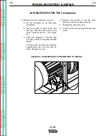
Page 68: ...h lift and secure the right and left side doors Note that there are latches at both ends of the door 3 With the 3 8 nut driver or socket wrench loosen the two screws on the left side of the alternator cover See Figure F 1 4 With the 3 8 socket wrench remove the screw and lock washer from the top center of the alternator cover See Figure F 1 5 With the 3 8 socket wrench loosen the two screws on the...

Page 69: ...SA 250 FIGURE F 2 MEASURING ROTOR RESISTANCE 8 Working from the left side of the machine measure the resistance across the rotor slip rings A Set the ohmmeter on the low scale X1 B Place one meter probe on one of the rotor slip rings Place the other probe on the other slip ring See Figure F 2 C Check the resistance across the slip rings It should read approximately 41 ohms ALTERNATOR ROTOR TEST co...

Page 70: ... the high scale X100 000 B Place one probe on either of the rotor slip rings Place the other probe on any good unpainted ground See Figure F 3 C Check the resistance It should read very high at least 0 5 megohm 500 000 ohms If the test does not meet the resistance specifications then the rotor may be faulty Replace the rotor 10 Replace the brushes on the slip rings Make sure they are seated correc...

Page 71: ...the technician or machine operator and will invalidate your factory warranty For your safety and to avoid elec trical shock please observe all safety notes and precautions detailed throughout this manual If for any reason you do not understand the test procedures or are unable to perform the test repairs safely contact the Lincoln Electric Service Department for electrical troubleshoot ing assista...

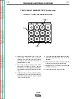
Page 72: ... REPAIR F 18 F 18 SA 250 FIELD SHUNT WINDING TEST continued FIGURE F 4 PLUG P10 LOCATIONS PLUG P10 TEST PROCEDURE 1 Turn engine off 2 Unlatch lift and secure the right side door Note that there are latches at both ends of the door 3 Locate plug P10 See Figure F 4 4 Remove plug P10 See Figure F 4 5 Locate the blue lead U pin 3 and the brown lead N pin 5 in the harness plug See Figure F 5 ...

Page 73: ...e resistance from either lead blue or brown to ground Set the volt ohmmeter on the high scale X100 000 This resistance should be at least 500 000 ohms 8 If the test does not meet the resistance specifications then check the harness plug and inline connectors for loose connec tions or shorted leads 9 If the plug and associated leads are okay then the shunt field coils may be faulty Replace 10 If th...

Page 74: ...tor and will invalidate your factory warranty For your safety and to avoid elec trical shock please observe all safety notes and precautions detailed throughout this manual If for any reason you do not understand the test procedures or are unable to perform the test repairs safely contact the Lincoln Electric Service Department for electrical troubleshoot ing assistance before you proceed Call 216...

Page 75: ...id See Figure F 6 and the Wiring Diagram Using the 5 16 wrench remove the leads from the solenoid 5 Using the external voltage supply apply 12VDC to the idler solenoid terminals Attach positive to the terminal where lead 56 was connected The solenoid should activate 6 The solenoid should deactivate when the 12VDC is removed 7 If the solenoid does not operate properly check for a mechanical restric...

Page 76: ...l shock please observe all safety notes and precautions detailed throughout this manual If for any reason you do not understand the test procedures or are unable to perform the test repairs safely contact the Lincoln Electric Service Department for electrical troubleshoot ing assistance before you proceed Call 216 383 2531 or 1 800 833 9353 WELD TEST DESCRIPTION If the machine output is low or hig...

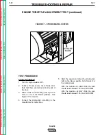
Page 77: ...e welder OFF 2 Unlatch lift and secure the left side door Note that there are latches at both ends of the door 3 With a white or red marking pencil place a mark on one of the blower paddles See Figure F 7 for location 4 Connect the strobe tach according to the manufacturer s instructions 5 Start the engine and direct the strobe tach light on the blower paddle Synchronize it to the rotating mark Wi...

Page 78: ...Avoid breaking the seal There should be enough play to allow adjustment without disturbing the seal Turn the threaded screw counter clockwise to increase the HIGH IDLE speed Adjust the speed until the fre quency reads 60 Hz Retighten the locking nut Adjust LOW IDLE First make sure there is no load on the machine Set the IDLE switch to AUTO and wait for the engine to change to low idle speed Use th...

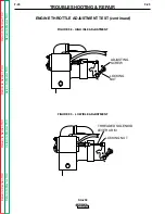
Page 79: ...urn to Master TOC Return to Master TOC Return to Master TOC Return to Master TOC TROUBLESHOOTING REPAIR F 25 F 25 SA 250 ENGINE THROTTLE ADJUSTMENT TEST continued FIGURE F 8 HIGH IDLE ADJUSTMENT LOCKING NUT ADJUSTING SCREW FIGURE F 9 LOW IDLE ADJUSTMENT LOCKING NUT THREADED SOLENOID LEVER ARM ...

Page 80: ...perator and will invalidate your factory warranty For your safety and to avoid elec trical shock please observe all safety notes and precautions detailed throughout this manual If for any reason you do not understand the test procedures or are unable to perform the test repairs safely contact the Lincoln Electric Service Department for electrical troubleshoot ing assistance before you proceed Call...

Page 81: ...lips connect the negative terminal of the 12 volt automotive battery to the negative brush holder This is the brushholder nearest the rotor lamination See Figure F 10 and the Wiring Diagram DO NOT remove brush holder 6 With the engine OFF use the other lead with alligator clips and touch the positive battery terminal to the positive brushholder Then disconnect the leads to remove the battery from ...

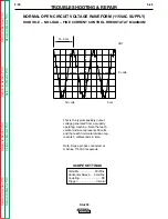
Page 82: ...e generated from a properly operating machine Note that each vertical division represents 50 volts and that each horizontal division rep resents 5 milliseconds in time Note Scope probes connected at machine 115VAC receptacle SCOPE SETTINGS Volts Div 50V Div Horizontal Sweep 5 ms Div Coupling DC Trigger Internal NORMAL OPEN CIRCUIT VOLTAGE WAVEFORM 115VAC SUPPLY HIGH IDLE NO LOAD FINE CURRENT CONTR...

Page 83: ...rated from a properly operating machine Note that each vertical divi sion represents 50 volts and that each horizontal division represents 5 milliseconds in time Note Scope probes connected at machine output terminals SCOPE SETTINGS Volts Div 50V Div Horizontal Sweep 5 ms Div Coupling DC Trigger Internal NORMAL OPEN CIRCUIT DC WELD VOLTAGE WAVEFORM HIGH IDLE NO LOAD FINE CURRENT CONTROL RHEOSTAT A...

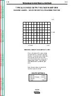
Page 84: ...ting machine Note that each vertical divi sion represents 20 volts and that each horizontal division represents 5 milliseconds in time The machine was loaded with a resistance grid bank Note Scope probes connected at machine output terminals SCOPE SETTINGS Volts Div 20V Div Horizontal Sweep 5 ms Div Coupling DC Trigger Internal TYPICAL DC WELD OUTPUT VOLTAGE WAVEFORM MACHINE LOADED SELECTOR SWITCH...

Page 85: ...hine operator and will invalidate your factory warranty For your safety and to avoid elec trical shock please observe all safety notes and precautions detailed throughout this manual If for any reason you do not understand the test procedures or are unable to perform the test repairs safely contact the Lincoln Electric Service Department for electrical troubleshoot ing assistance before you procee...

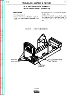
Page 86: ... REPLACEMENT continued FIGURE F 11 FRONT PANEL REMOVAL REMOVE FASTENERS BATTERYRETAINER FASTENERS TERMINAL CABLES PROCEDURE 1 Turn the engine off 2 Unlatch lift and secure the left and right side doors There are latches on both sides of the doors 3 With the 1 2 wrench disconnect the negative battery cable 4 With the 1 2 wrench remove the four bolts and washers from the panel located below the cont...

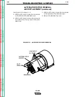
Page 87: ...EPLACEMENT continued FIGURE F 12 ALTERNATOR COVER REMOVAL LOOSEN 5 SCREWS ALTERNATOR COVER SLIP RINGS BRUSHES See Figure F 12 for steps 5 8 5 With the 3 8 wrench loosen the two screws on the left side of the alternator cover 6 With the 3 8 wrench remove the screw and lock washer from the top center of the alter nator cover 7 With the 3 8 wrench loosen the two screws on the right side of the altern...

Page 88: ...VE COLLAR BENT WASHER BRUSH HOLDER ASSEMBLY See Figure F 13 for steps 9 11 9 With the 7 16 wrench remove the two bolts nuts and washers mounting the brush holder assembly to the stator frame 10 Bend the flat washer away from the rotor locking nut 11 With the 1 5 8 socket wrench remove the rotor locking nut washer and sleeve collar NOTE The sleeve collar will have to be removed with a gear puller B...

Page 89: ...ng the exciter brushes in their holders twist the brush pigtail at its entrance to the brush until the strands are tightly packed and no part of the pigtail protrudes beyond the brush surface in the pigtail slot When the brush is placed in the holder clear the pigtail from the side of the holder to allow free radial move ment of the brush d The exciter brush spring must lie flat on the corner of t...

Page 90: ... operator and will invalidate your factory warranty For your safety and to avoid elec trical shock please observe all safety notes and precautions detailed throughout this manual If for any reason you do not understand the test procedures or are unable to perform the test repairs safely contact the Lincoln Electric Service Department for electrical troubleshoot ing assistance before you proceed Ca...

Page 91: ...ator cover 7 With the slot head screwdriver remove the commutator wrap around See Figure F 14 8 Disconnect the yellow and white wires at the in line connectors See the Wiring Diagram and Figure F 15 9 Disconnect the two yellow leads One is located at the field bridge and the other at the field fuse holder Cut any necessary cable ties See Figure F 15 10 Remove the tape and using the 3 8 wrench and ...

Page 92: ... REPAIR F 38 F 38 SA 250 FIGURE F 15 LEAD DISCONNECTION POINTS YELLOW AND WHITE WIRE IN LINE CONNECTORS YELLOW LEADS BLACK CURRENT TRANSFORMER LEAD ALL LOCATED BEHIND CASE FRONT ALTERNATOR STATOR REMOVAL AND REPLACEMENT continued FIGURE F 16 LEAD DISCONNECTION CIRCUIT BREAKER RECEPTACLES FIELD BRIDGE RECTIFIER 230 VAC RECEPTACLE 115 VAC RECEPTACLE CIRCUIT BREAKER FIELD BRIDGE RECTIFIER ...

Page 93: ... tor Note the position of the brushes for reassembly TROUBLESHOOTING REPAIR F 39 F 39 SA 250 ALTERNATOR STATOR REMOVAL AND REPLACEMENT continued FIGURE F 17 GENERATOR BRUSH HOLDER CABLE REMOVAL GENERNATOR BRUSH HOLDER COIL CABLES 4 17 With the 1 2 wrench disconnect and clear the four heavy cables from the gen erator brush holders to the coils in the generator frame It is not necessary to remove th...

Page 94: ...e four mounting bolts adjust and re tighten if necessary 23 Tighten the generator brush holder assembly with the 7 16 wrench Note brush holder drill spot 24 Connect the four heavy cables from the generator frame coils to the generator brush holders 25 Install the eight commutator brushes according to how you marked their posi tions at disassembly 26 Attach the black lead to the positive termi nal ...

Page 95: ...achine operator and will invalidate your factory warranty For your safety and to avoid elec trical shock please observe all safety notes and precautions detailed throughout this manual If for any reason you do not understand the test procedures or are unable to perform the test repairs safely contact the Lincoln Electric Service Department for electrical troubleshoot ing assistance before you proc...

Page 96: ...tator Removal procedure See Figure F 19 for steps 4 10 4 Turn off the fuel at the fuel bowl and remove the fuel line Plug the line to prevent spillage 5 Remove the fuel return line from the top of the fuel tank 6 With the 9 16 wrench remove the four nuts bolts and washers that mount the fuel tank to the rails 7 Slightly lift the fuel tank and remove the cable retainer You will need a large screw d...

Page 97: ...d to the selector switch 15 Disconnect the current transformer black lead from circuit breaker CB2 16 Remove the two blue current transformer leads from the idler PC board Note lead location TROUBLESHOOTING REPAIR F 43 F 43 SA 250 Return to Section TOC Return to Section TOC Return to Section TOC Return to Section TOC Return to Master TOC Return to Master TOC Return to Master TOC Return to Master T...

Page 98: ...ch side 19 Carefully clear all remaining leads and lift up and set the front panel assembly to the left side of the machine Make sure all leads are clear TROUBLESHOOTING REPAIR F 44 F 44 SA 250 Return to Section TOC Return to Section TOC Return to Section TOC Return to Section TOC Return to Master TOC Return to Master TOC Return to Master TOC Return to Master TOC GENERATOR FRAME REMOVAL AND REPLAC...

Page 99: ...nerator frame away from the engine and armature assembly Be careful to support the generator frame as you remove it Replacement 24 Support the generator frame with the rope sling Mount the generator frame to the engine and armature assembly Before removing the rope sling be careful to sup port the generator frame with the wood or steel block under the engine adapter plate With the 9 16 wrench inst...

Page 100: ...4 Perform the replacement procedures according to each of the following Alternator Stator Removal and Replacement Alternator Rotor Removal and Replacement Before installing the machine case top and sides be sure to replace any cable ties cut during disas sembly TROUBLESHOOTING REPAIR F 46 F 46 SA 250 Return to Section TOC Return to Section TOC Return to Section TOC Return to Section TOC Return to ...

Page 101: ... the technician or machine operator and will invalidate your factory warranty For your safety and to avoid elec trical shock please observe all safety notes and precautions detailed throughout this manual If for any reason you do not understand the test procedures or are unable to perform the test repairs safely contact the Lincoln Electric Service Department for electrical troubleshoot ing assist...

Page 102: ...s and lock washers holding the blower paddles and the armature to the engine flywheel See Figure F 23 8 With the armature supported and balanced in the rope sling carefully rotate the armature 1 8 turn in either direction to release The armature is now free to be removed from the engine Replacement 9 Support the armature with the rope sling Mount the armature to the engine rotating it 1 8 of a tur...

Page 103: ...pair or replace any electrical components ENGINE OUTPUT Mode No Load RPM Load RPM Low Idle 1350 1400 NA High Idle 1780 1810 1700 1795 WELDER DC OUTPUT Current Control Current Selector Open Circuit Load Volts Load Amps Rheostat Switch Voltage Maximum Maximum 91 98 5 40 47 300 AC AUXILIARY POWER RECEPTACLE OUTPUT 230 Volt Receptacle 115 Volt Receptacle Open Circuit Load Volts Load Amps Open Circuit ...

Page 104: ...NOTES F 50 F 50 SA 250 Return to Section TOC Return to Section TOC Return to Section TOC Return to Section TOC Return to Master TOC Return to Master TOC Return to Master TOC Return to Master TOC ...

Page 105: ...o Master TOC Return to Master TOC Return to Master TOC Electrical Diagrams Section Section G Wiring Diagram G 2 Wiring Diagram Wire Feed Module G 3 Idler PC Board M13708 Schematic G 4 Idler PC Board M13708 Components G 5 TABLE OF CONTENTS ELECTRICAL DIAGRAMS SECTION ...

Page 106: ...NOTES SA 250 Return to Section TOC Return to Section TOC Return to Section TOC Return to Section TOC Return to Master TOC Return to Master TOC Return to Master TOC Return to Master TOC ...

Page 107: ...UT TERMINALS CONNECT TO POS NEG CONNECT TO NEG BRUSH HOLDER 608 609 2 HEAVY LEAD 8 LEAD NEGATIVE CV OUTPUT TERMINAL PANEL MACHINE MUST NOT BE RUNNING WHEN MAKING THESE CONNECTIONS ON MACHINE REMOVE PLUG P10 FROM CONNECTOR J5 CONNECT PLUG P5 ON W F M TO CONNECTOR J5 ON MACHINE PLUG P5 250 AMP THERMOSTAT ASSEMBLY INLINE CONNECTORS REMOTE CONTROL POTENTIOMETER BOX CLEVELAND OHIO U S A L9150 R GROUND ...

Page 108: ... W Y 510 POS NEG Y W 503 602 509 610 600 31 32 GND 31 32 GND 609 610A 510 501 75 503A 602 76 77 2 4 75A 4 2 4A 2A 77A WIRE FEED MODULE WIRING DIAGRAM 250 25W 30000 MFD 75 VOLT EACH 219 218 CONTROL BOARD SHOWN IN CV MODE CC CV SWITCH S1 LOCAL REMOTE SWITCH S2 SHUNT FIELD TO RHEOSTAT 115V DC 115V AC FLASHING LEADS SHOWN IN LOCAL MODE 77A 77B 77 621 219 218 621 300 AMP SHUNT P3 P4 P2 P1 1 2 3 4 5 6 9...

Page 109: ... U S A DR S16477 1 4W 022 50V CAPACITORS MFD WITHOUT AFFECTING THE INTERCHANGEABILITY OF A COMPLETE BOARD THIS DIAGRAM MAY N A SINCE COMPONENTS OR CIRCUITRY ON A PRINTED CIRCUIT BOARD MAY CHANGE R UNLESS OTHERWISE SPECIFIED ELECTRICAL SYMBOLS PER E1537 UNLESS OTHERWISE SPECIFIED P C BOARD IS CONNECTED DIRECTLY R Ch ge Sht No MATERIAL TOLERANCE t TO AGREE WITH PUBLISHED STANDARDS NOT SHOW THE EXACT...

Page 110: ...r TOC Return to Master TOC Return to Master TOC Return to Master TOC NOTE Lincoln Electric assumes no responsibility for liablilities resulting from board level troubleshooting PC Board repairs will invalidate your factory warranty Individual Printed Circuit Board Components are not available from Lincoln Electric This information is provided for reference only Lincoln Electric discourages board l...

Page 111: ...__________________________________ ___________________________________________________________________________ ___________________________________________________________________________ ___________________________________________________________________________ ___________________________________________________________________________ _____________________________________________________________...

Reviews: