CONNECTION OF THE LN-25 TO THE
SA-250 “ACROSS THE ARC”
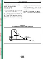
(SEE FIGURE C.4.)
1. Shut the welder off.
2. Connect the electrode cable from the LN-25 to the
“+” terminal of the welder. Connect the work cable
to the “CV–” terminal of the welder.
NOTE: Welding cable must be sized for current and
duty cycle of application.
NOTE: Figure C.4 shows the electrode connected for
positive polarity. To change polarity, shut the welder
off and reverse the electrode and work cables at the
SA-250 output terminals. Reverse the LN-25 polarity
switch.
3. Connect the K444-2 remote control cable to the 14
pin amphenol on the wire feed module.
4. Attach the single lead from the LN-25 control box
to the work using the spring clip on the end of the
lead. This is only a control lead — it carries no
welding current.
5. Place the IDLER switch in the “HIGH” position.
6. Adjust wire feed speed and voltage at the LN-25.
ACCESSORIES
C-7
C-7
SA-250
Retur
n to Section TOC
Retur
n to Section TOC
Retur
n to Section TOC
Retur
n to Section TOC
Retur
n to Master TOC
Retur
n to Master TOC
Retur
n to Master TOC
Retur
n to Master TOC
FIGURE C.4
SA-250/LN-25 ACROSS THE ARC CONNECTION DIAGRAM
TO
WORK
14 PIN
AMPHENOL
WORK CLIP
LEAD TO WORK
LN-25 WIRE FEEDER
WITH K444-2 REMOTE
VOLTAGECONTROL OPTION
ELECTRODE CABLE
CV-
+

