Lincoln Electric RED-D-ARC IM648-B Operator'S Manual Download Page 31

F-2

DIAGRAMS

F-2

PYTHON

L10936

10K

5

5

212

10

219

13

14

212

1

POWER

U

-

ELEC

XFER

X40

X4

5,6 AIR SOL 7,8 ELEC SOL

J34

J32

3 TRIGGER

11

12

CHOKE

0.6A

5

TP3

B

N

CASE FRONT

BASE

PROTECTIVE BONDING CIRCUIT

A

A

4

S

LEFT SIDE OF MACHINE

S

BK-IN

2

R

218

3

S

BK-OUT

217

S3

PSI_SET

302

E

C

51

404

R

N

CONTROL

8

D

R

214

10

B
A

X1

S2

RESET

347

7

1

J4,J10, J30

4

J40

5

L1

S

404

6


J1

16

8

W

503

15

7

223

R


W

6

R

V

W

W

G

N

61

H1

FAN

1

INPUT

BRIDGE

RF

TOROID

1

C

B

A

7

6

18V

J40

348

276

6

8

215

9

219

213

4
9

FRONT OF MACHINE

277B

3

18V

P_XFMR

7

8

344

2W

221

S1

310

1,4 24V

2 ELEC SOL

J30

12V

FR-

IN

S

+15V

RIGHT SIDE OF MACHINE

H2

-

F

207

E

J2

501

505

502

RELAY

++VOLT

208

H1

218

T2

2
7

J22

6

9

54

FR-

IN

R

312

BK-IN

354

BK-OUT

N

CONNECTOR CAVITY NUMBERING SEQUENCE

14 GND

13

14

5

1

2

6

3

7

4

2
5

56

53

3
6

440-

E

S

xxxxxxx

N.C.  PLACE "A" LEAD ON APPROPRIATE CONNECTION FOR INPUT VOLTAGE. 

CONNECTION SHOWN IS FOR 440-460V OPERATION.

N.D.  C1  AND  C2 CAPACITORS ARE A MATCHED SET.  

3

6

4

5

OUTPUT

51

7

1

PC BOARD

303

9

1

8

309

FOR THREE PHASE INPUT: GROUND MACHINE PER NATIONAL AND LOCAL ELECTRICAL CODES.

CONNECT TERMINALS U, V & W TO SUPPLY CIRCUIT.

N.B.  SINCE COMPONENTS OR CIRCUITRY OF A PRINTED CIRCUIT BOARD MAY CHANGE WITHOUT AFFECTING

THE INTERCHANGEABILITY OF A COMPLETE BOARD, THIS DIAGRAM MAY NOT SHOW THE EXACT

COMPONENTS OR CIRCUITRY HAVING A COMMON CODE NUMBER.

3000/450

C2

2
5


POWER

S4 PRIMARY RECONNECT

MOTOR

 FAN

FAN

E

11

3

302

4

J33

J1,J20 J33

277A


XFMR

MAIN

506

202

209

205

N.A.

PER 

INPUT 

6

1

9

CT

3

PSI SET

4

J4

RELAY

++VOLT

J3

7,8 ELEC SHUNT (TWIST PR)

W

2

XFER

 12 GND

11 TRIGGER

2,6 PSI SWITCH 10 ELEC SOL

9 AIR SOL

3

A

X20

X40

X30

X3

X20

5
1

4

7

 3 NOZZLE

2

X2

2

J5

347

J
I

H
G

64

2

206

202

U

A


A

B

D1

201

204

+

-

4A

M
L

9

PRESSURE

WORK

Y

361

14

366

12

J32

213

15

216

N.C.

J20

4

2

H3

H2

200-

220-

W

208V

230V

380-

460V

4

2

H5

H4

54

OUTPUT

8

16

READY LED

LOW_PSI LED

POT WIPER

RESET

GND

RESET LED

THERMAL LED

  P-UF

9

2

J2,J21,J31

U = BLUE

W

1
3

364

369

N = BROWN

11

223

306

216

277A

8

X2

C1

3000/450

E

6

364

FAN

FAN

354

3

348

344

343

FR-OUT

309

306

D

INTERFACE RECEPTACLE

3

4

275

7

210

214

217

R

202

I

+

507

277

DISPLAY

365

6

4A

2A

1

2A


N

2

4
9

S5

4

10

1

361

5

206

B21

SHOWN FOR 400-460VAC OPERATION

X4

207A

SLOW BLOW

18V

209

A

 T1

1

3

X10

U

7

R

W

H4

24V

4

2

Y

401

505

506

4

W

310

F

8

H3

TP2

REAR OF MACHINE

18V

3

4,5 XFER SHUNT (TWIST PR)

CONTROL

N

365

ELEC

215

I

208

Y

204

K

(VIEWED FROM COMPONENT SIDE OF BOARD)

COLOR CODE:

B = BLACK

G = GREEN

R = RED

W = WHITE

503
3

6

  CURRENT

1

4

206

203

205

W

415V

NOTES:

N.A.

1. FOR MACHINES SUPPLIED WITH INPUT CABLE

FOR SINGLE PHASE INPUT: CONNECT GREEN LEAD TO GROUND PER NATIONAL ELECTRIC CODE.

CONNECT BLACK & WHITE LEADS TO SUPPLY CIRCUIT.

WRAP RED LEAD WITH TAPE TO PROVIDE 600V. INSULATION.

FOR THREE PHASE INPUT: CONNECT GREEN LEAD TO GROUND PER NATIONAL ELECTRIC CODE.

CONNECT BLACK, RED & WHITE LEADS TO SUPPLY CIRCUIT.

2. FOR MACHINES NOT SUPPLIED WITH INPUT CABLE

FOR SINGLE PHASE INPUT: GROUND MACHINE PER NATIONAL AND LOCAL ELECTRICAL CODES.

CONNECT TERMINALS U & W TO SUPPLY CIRCUIT.

360

TSTAT

207

+

J10

P_XFMR

  10 WORK

8 AIR SOL

13 IGBT

401

J31

1

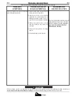
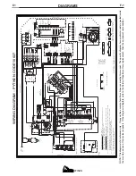
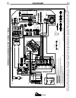
WIRING DIAGRAM - PYTHON CODE 10656

TRANSFORMER

AIR

SOLENOID

J5,J22, J34

360

3

S

369

2

7

2

366

4
8

S

62 
61

6

312

S

FAN

Y

203

10

6

ELECTRICAL SYMBOLS PER E1537


343

502

4

J21

B

115V

1

Y

TRANSFORMER

Y = YELLOW

 AUXILIARY

H6

12V

53

8

5
2

1

13

5

12

10

1,2 TRIGGER

4 ELECTRODE

501

507

62

5

8

N

3 IGBT

2

303

2

POT

221

277

CW (MAX)

R1

B

276

275

210

J3

FR-OUT

xxxxxxx

203

207A

201

T3

56

64

C

H5

C

207A

TP1

7

14

1

8

4

8

1

5

3

6

1

Y

Y

4

2

1

4

15

3

5

10

1

NOTE:  This diagram is for reference only.   It may not be accurate for all machines covered by this manual.  The specific diag

ram for a particular code is pasted inside

the machine on one of the enclosure panels.  If the diagram is illegible, write to the Service Department for a replacement.  G

ive the equipment code number..

Summary of Contents for RED-D-ARC IM648-B

Page 1: ...n mind However your overall safety can be increased by proper installation and thoughtful operation on your part DO NOT INSTALL OPERATE OR REPAIR THIS EQUIPMENT WITHOUT READING THIS MANUAL AND THE SAFETY PRECAUTIONS CONTAINED THROUGHOUT And most importantly think before you act and be careful For use with machines having Code Numbers 10627 10656 11025 11026 North America s Largest Fleet of Welding...

Page 2: ... spatter or metal ELECTRIC SHOCK can kill 1 a The electrode and work or ground circuits are electrically hot when the power source is on Do not touch these hot parts with your bare skin or wet clothing Wear dry hole free gloves to insulate hands 1 b When the power source is operating voltages in excess of 250 volts are produced This creates the potential for serious electrical shock potentially ev...

Page 3: ...ized Electric and Magnetic Fields EMF Cutting or gouging current cre ates EMF fields around torch cables and cutting machines 8 b EMF fields may interfere with some pacemakers so opera tors having a pacemaker should consult their physician before cutting or gouging 8 c Exposure to EMF fields during cutting or gouging may have other health effects which are now not known 8d All operators should use...

Page 4: ...PYTHON iii NOTES iii ...

Page 5: ... appropriés et non inflammables 4 Des gouttes de laitier en fusion sont émises de l arc de soudage Se protéger avec des vêtements de protection libres de l huile tels que les gants en cuir chemise épaisse pan talons sans revers et chaussures montantes 5 Toujours porter des lunettes de sécurité dans la zone de soudage Utiliser des lunettes avec écrans lateraux dans les zones où l on pique le laitie...

Page 6: ...tion below for future reference This information can be found on your machine nameplate Product _________________________________________________________________________________ Model Number ___________________________________________________________________________ Code Number or Date Code_________________________________________________________________ Serial Number______________________________...

Page 7: ...ons A 5 Output Connections A 5 Torch Connection A 5 Operation Section B Safety Precautions B 1 Description B 1 Preheat Temperature for Plasma Cutting B 1 User Responsibility B 2 Recommended Processes and Equipment B 2 Operational Features and Controls B 2 Design Features and Advantages B 2 Cutting Capability B 3 Consumable Life B 3 Limitations B 4 Controls and Settings B 4 Pilot Arc Discussion B 6...

Page 8: ...tor Discharge Procedure D 1 Routine Maintenance D 2 Periodic Maintenance D 2 Troubleshooting Section E Safety Precautions E 1 How to Use Troubleshooting Guide E 1 Troubleshooting Guide E 2 Wiring Diagrams Section F Wiring Diagrams F 1 thru F 3 Dimension Print F 4 Parts List P342 Series P210 K ...

Page 9: ... Output Model 208 230 460 87 81 48 50 60Hz INPUT RECOMMENDED INPUT WIRE AND FUSE SIZES Type 75 C Type 75 C Copper Fuse Copper Ground Superlag Wire in Wire in Input Voltage or Conduit Conduit and Breaker AWG IEC AWG IEC Frequency 1 Size Sizes Sizes 208 50 60 60 8 8 4mm2 8 8 4mm2 230 50 60 60 8 8 4mm2 8 8 4mm2 460 50 60 40 10 6mm2 10 6mm2 575 50 60 30 10 6mm2 10 6mm2 Type 75 C Type 75 C Copper Fuse ...

Page 10: ...ING Either the front or rear handles or both may be used to lift or move the machine DO NOT use the pull handle on the optional undercar riage if installed to lift the machine This handle is not designed to support the full weight of the machine and using it to lift the machine could cause personal injury or damage to the machine TILTING The PYTHON must be placed on a stable level sur face so it w...

Page 11: ...the line switch out of the case front 5 Angle the line switch so the nuts on the switch can be loosened 6 Remove the cord from the switch 7 Remove the nut lock washer plain washer and green lead off of the ground screw assembly 8 Loosen the cable connector on the case back 9 Pull the line cord out of the machine CORD INSTALLATION 1 Feed the new cord through the cable connector and into the machine...

Page 12: ...e used on engine driven power supplies However the following AC Wave Form Voltage and Input Power Restrictions do apply AC Wave Form Restrictions The PYTHON can be operated on engine driven gen erators as long as the engine drive output meets the following conditions The AC wave form frequency is between 45 and 65 Hz For 200 230 VAC Supplies The AC wave form peak voltage must be below 420 volts Th...

Page 13: ...a noticeable pressure drop in the line Filter elements should be replaced when a pressure drop of 8 10 psi is indicated however for optimum performance of the PRO CUT the filter element should be replaced at or before the pres sure drop reaches 8 psi Be sure to select a prefilter that will accommodate the necessary flow rating for the PRO CUT as specified in the Installation sec tion of this instr...

Page 14: ...ure problems associated with hi frequency start systems The PYTHON is capable of cutting with nitrogen or air The PYTHON is controlled by a microprocessor based control board The machine performs rudimen tary self troubleshooting when powered up which aids in field servicing PREHEAT TEMPERATURE FOR PLASMA CUTTING Preheat temperature control is not necessary in most applications when plasma arc cut...

Page 15: ...lities so that you can get maximum use from your machine Portable design for industrial use Continuous output control 35 85 amps Reliable touch start mechanism for plasma arc initi ation Unique microprocessor controlled starting sequence for safe and consistent starting Rapid arc transfer for fast cutting of expanded metal High transfer distance for ease of use Soft start of input filter capacitor...

Page 16: ...ng of 80 amps at an approximate speed of 35 IPM PYTHON Mild Steel Cut Capacity Chart Recommended Torch Travel Speed IPM 80 of Maximum Speed 100 80 60 40 20 0 0 000 0 125 0 250 0 375 0 500 0 625 0 750 Material Thickness 25 A 35 A 55 A 1 00 80 A Figure B 1 CONSUMABLE LIFE The expected life for the PYTHON s electrode under normal operating conditions is approximately 160 starts cuts An erosion of 060...

Page 17: ... pressure after the air turns off but this is normal Do NOT reset the pressure while the air is NOT flowing 3 PREPARING TO CUT When ready to cut place the torch near the work make certain all safety precautions have been taken and pull the trigger The air will flow for a preflow time of 2 seconds and the pilot arc will start This is true unless the machine is in postflow then the preflow time is s...

Page 18: ...OMATICALLY WITHOUT DEPRESS ING THE RESET BUTTON Check the assembly of the torch consumables If they are not properly in place the machine will not start Make sure that the shield cup is hand tight Do not use pliers or over tighten Check the conditions of the inside of the nozzle If debris has collected rub the electrode on the inside bottom of the nozzle to remove any oxide layer that may have bui...

Page 19: ... be dragged on the metal sur face touching it lightly to the surface after pierc ing a hole 2 CURRENT CONTROL SHOULD BE SET BELOW THE MID RANGE Do not allow cable or body to contact hot sur face THICK SECTIONS OF METAL 1 OUTPUT SET ABOVE 45 AMPS The best quality and consumable life will be obtained by holding the torch off the surface about 3 16 Too long an arc may compromise cut quality and consu...

Page 20: ...igher or lower pressure will cause turbulence in the plasma arc eroding the orifice of the nozzle tip i Use only Lincoln consumable parts These parts are patented and using any other replacement consumables may cause damage to the torch or reduce cut quality MACHINE INTERFACE The PYTHON comes standard with a machine inter face Interface signals provided include arc start arc initiated and arc volt...

Page 21: ...nly Provides Torch and Work Cable storage S22147 043 VORTECH nozzle with an 043 1 2 mm Orifice for 35 60 Amps S22147 053 VORTECH nozzle with an 053 1 3 mm Orifice for 60 85 Amps S22147 082 VORTECH nozzle with an 082 2 1 mm Orifice for Gouging at 60 85 Amps S22149 Electrode replacement electrodes for cut ting S22150 Shield Cup This shields the torch tip and provides more visibility to the workpiece...

Page 22: ... body of the resistor and connect resistor leads across the two capacitor terminals Hold resistor in place for 10 seconds DO NOT TOUCH CAPACITOR TERMINALS WITH YOUR BARE HANDS 7 Repeat discharge procedure for the other capaci tor 8 Check voltage across terminals of all capacitors with a DC voltmeter Polarity of capacitor terminals is marked on PC board above terminals Voltage should be zero If any...

Page 23: ...ieve any so as not to restrict the flow of air to the torch PERIODIC MAINTENANCE Change consumables as required 1 Thermal Protection Two thermostats protect the machine from excessive operating temperatures Excessive temperatures may be caused by a lack of cooling air or operating the machine beyond the duty cycle and output rating If excessive operating temperatures should occur the yellow therma...

Page 24: ...om Step 3 RECOMMENDED COURSE OF ACTION This column provides a course of action for the Possible Cause generally it states to contact you local Lincoln Authorized Field Service Facility If you do not understand or are unable to perform the Recommended Course of Action safely contact you local Lincoln Authorized Field Service Facility HOW TO USE TROUBLESHOOTING GUIDE Service and Repair should only b...

Page 25: ...vitated 1 Check the input power to be sure it is on 2 Check the power line fuses and machine connection 3 Disconnect input power at fuse panel and check line switch conti nuity Replace line switch if bad 4 Auxiliary transformer may be faulty 1 Auxiliary transformer may be faulty 2 Disconnect input power from the machine Check that connectors on harness between Control Bd and Display Bd are properl...

Page 26: ...heck or replace c Possible faulty Output Power board d Possible faulty Control board 2 check for continuity from the bulk head connector to the molex See Wiring Diagram 3 Remove the handles or barrel of the torch and examine all the con nections Pay attention to location of electrode lead mounting at back of torch head broken trigger and solenoid leads 4 Check for proper trigger switch operation R...

Page 27: ... in the torch cable Replace cable as needed 4 If a slight thump cannot be felt in the torch when the trigger is pulled check for loose connection in the torch head and solenoid assembly 5 With machine turned off input power removed and torch and consumables connected mea sure resistance on Output Power board between B1 and B21 If 10Ω possible fault in torch and cable assembly 6 Possible fault in O...

Page 28: ...COMMENDED COURSE OF ACTION Pilot arc starts but will not transfer when brought near work 1 Check work lead connection for clean secure connection 2 Plasma will only cut conductive material Do not attempt to cut fiberglass plastic rubber PVC or any other non conductive material 3 Make sure work piece is clean and dry Remove any scale rust or dross 4 Check all connections to Output board 5 Possible ...

Page 29: ...Control board 1 Make sure there is a Lincoln torch and cable assembly connect ed properly to the PYTHON bulk head connector 2 Check consumables for proper installation or excessive wear Replace if excessively worn If not use a piece of fine emery cloth to remove any oxide buildup on the tip of the electrode 1 Press the Reset button If torch and consumables are properly installed the Safety LED sho...

Page 30: ...348 1 8 2 9 309 3 S xxxxxxx 2 6 8 FOR THREE PHASE INPUT CONNECT GREEN LEAD TO GROUND PER NATIONAL ELECTRIC CODE CONNECT BLACK RED WHITE LEADS TO SUPPLY CIRCUIT 2 FOR MACHINES NOT SUPPLIED WITH INPUT CABLE 201 10 219 WORK 503 216 213 502 7 4 210 10 2000 500 FOR THREE PHASE INPUT GROUND MACHINE PER NATIONAL AND LOCAL ELECTRICAL CODES CONNECT TERMINALS U V W TO SUPPLY CIRCUIT THE INTERCHANGEABILITY O...

Page 31: ...V 4 2 H5 H4 54 OUTPUT 8 16 READY LED LOW_PSI LED POT WIPER RESET GND RESET LED THERMAL LED P UF 9 2 J2 J21 J31 U BLUE W 1 3 364 369 N BROWN 11 223 306 216 277A 8 X2 C1 3000 450 E 6 364 FAN FAN 354 3 348 344 343 F R O U T 309 306 D INTERFACE RECEPTACLE 3 4 275 7 210 214 217 R 202 I 507 277 DISPLAY 365 6 4A 2A 1 2A N 2 4 9 S5 4 10 1 361 5 206 B21 SHOWN FOR 400 460VAC OPERATION X4 207A SLOW BLOW 18V ...

Page 32: ... 216 277A 8 X2 C1 3000 450 FAN FAN F R O U T 309 306 D INTERFACE RECEPTACLE 3 4 275 7 210 214 217 R 202 I 507 277 DISPLAY 6 1 2A N S5 206 B21 SHOWN FOR 400 460VAC OPERATION X4 207A SLOW BLOW 18V 209 T1 1 3 X10 U 7 R W H4 24V 4 2 Y 401 505 506 4 W 310 F 8 H3 TP2 REAR OF MACHINE 18V 3 4 5 XFER SHUNT TWIST PR CONTROL N 365 ELEC 215 I 208 Y 204 K VIEWED FROM COMPONENT SIDE OF BOARD COLOR CODE B BLACK ...

Page 33: ...CIRCUITRY OF A PRINTED CIRCUIT BOARD MAY CHANGE WITHOUT AFFECTING COMPONENTS OR CIRCUITRY HAVING A COMMON CODE NUMBER CONNECTION SHOWN IS FOR 550 575V OPERATION N C PLACE A LEAD ON APPROPRIATE CONNECTION FOR INPUT VOLTAGE Y 404 6 B O T I N R X4 2000 500 205 241 575V H6 H5 460V 440 A A 2 4 1 C1 E XFER 2 277B 18V B E 201 13 T O P I N W 221 S3 R PSI_SET 1 344 S1 201A COLOR CODE B BLACK OR GRAY G GREE...

Page 34: ...F 5 DIAGRAMS F 5 PYTHON 16 41 22 50 3 50 13 71 29 50 CC UF M19195 DIMENSION PRINT PYTHON PYTHON ...

Page 35: ...electrically live parts or electrode with skin or wet clothing Insulate yourself from work and ground No toque las partes o los electrodos bajo carga con la piel o ropa moja da Aislese del trabajo y de la tierra Ne laissez ni la peau ni des vête ments mouillés entrer en contact avec des pièces sous tension Isolez vous du travail et de la terre Berühren Sie keine stromführenden Teile oder Elektrode...

Page 36: ...gute Be und Entlüftung des Arbeitsplatzes Mantenha seu rosto da fumaça Use ventilação e exhaustão para remover fumo da zona respiratória Turn power off before servicing Desconectar el cable de ali mentación de poder de la máquina antes de iniciar cualquier servicio Débranchez le courant avant l entre tien Strom vor Wartungsarbeiten abschalten Netzstrom völlig öff nen Maschine anhalten Não opere co...

Page 37: ...s and Service through Subsidiaries and Distributors Worldwide Cleveland Ohio 44117 1199 U S A TEL 216 481 8100 FAX 216 486 1751 WEB SITE www lincolnelectric com World s Leader in Welding and Cutting Products ...

Reviews: