


Retur
n to Section TOC
Retur
n to Section TOC
Retur
n to Section TOC
Retur
n to Section TOC
Retur
n to Master TOC
Retur
n to Master TOC
Retur
n to Master TOC
Retur
n to Master TOC
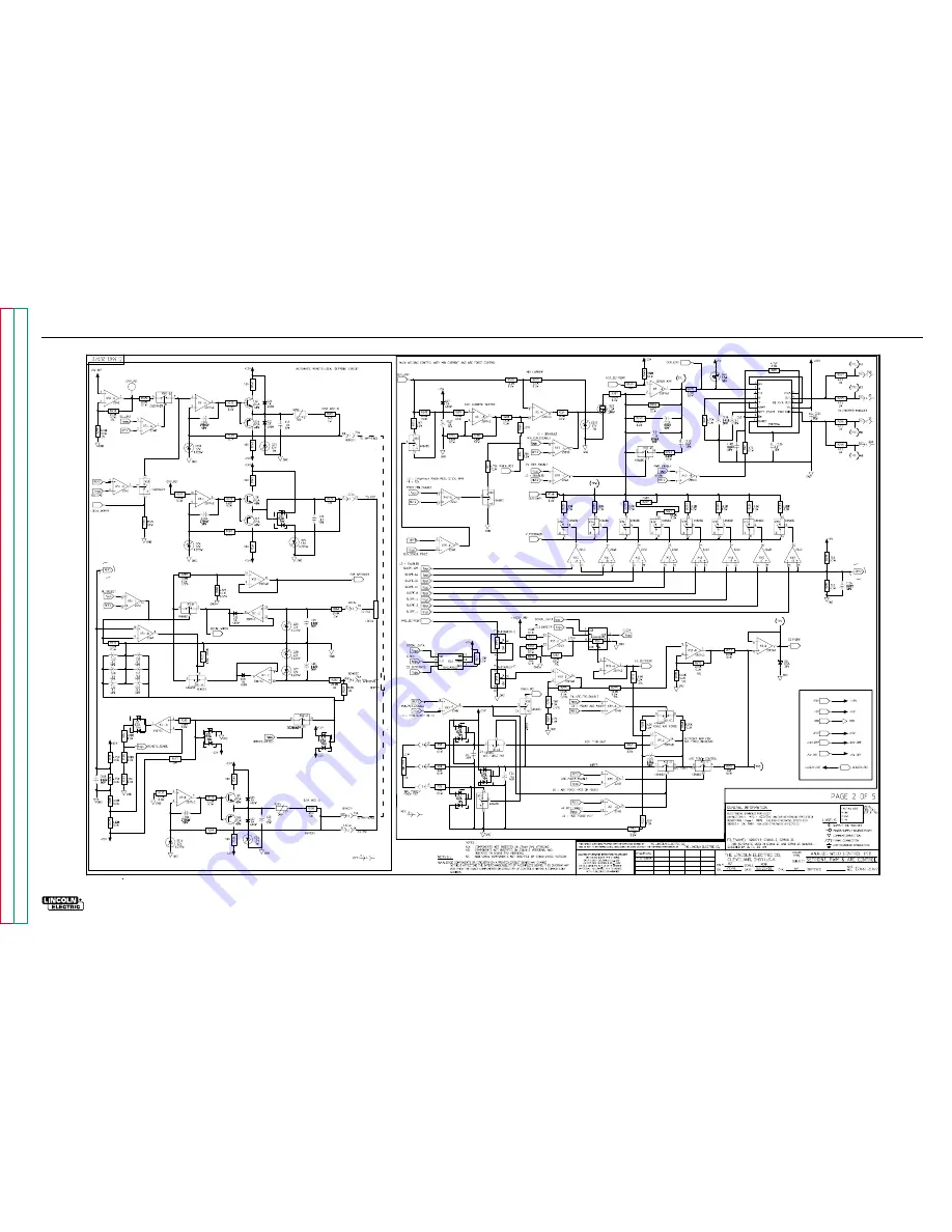
ELECTRICAL DIAGRAMS
G-12
RANGER 250
SCHEMATIC - WELD CONTROL PRINTED CIRCUIT BOARD - SHEET 2
G-12
NOTE: This diagram is for reference only. It may not be accurate for all machines covered by this manual.