Lincoln Electric RANGER 10-LX Service Manual Download Page 124

Retur

n to Section TOC

Retur

n to Section TOC

Retur

n to Section TOC

Retur

n to Section TOC

Retur

n to Master TOC

Retur

n to Master TOC

Retur

n to Master TOC

Retur

n to Master TOC

TROUBLESHOOTING & REPAIR

F-70

F-70

RANGER 10-LX

RETEST AFTER REPAIR

Retest a machine:

•  If it is rejected under test for any reason that requires you to remove any mechanical part which could affect the

machine’s electrical characteristics.   OR

•  If you repair or replace any electrical components.    
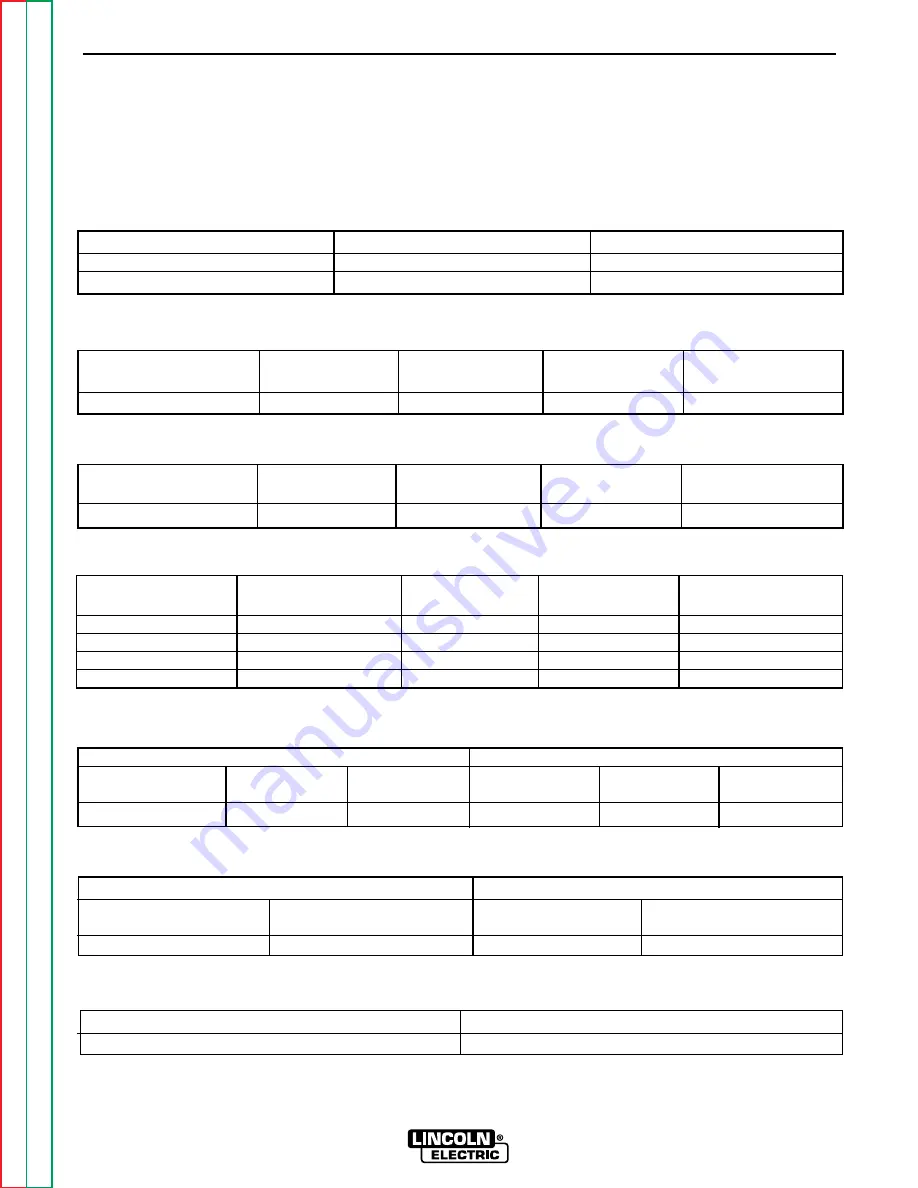
ENGINE OUTPUT

Mode

No Load RPM

Load RPM

Low Idle

2150-2250

NA

High Idle

3650-3700

3400-3650

WELDER DC OUTPUT

1

Output Control

Range Switch

Open Circuit

Load Volts

Load Amps

Volts

Maximum

Maximum

61 - 68

25 - 35

250 - 285

WELDER AC OUTPUT

1

Output Control

Range Switch

Open Circuit

Load Volts

Load Amps

Volts

Maximum

Maximum

70 - 76

25 - 35

250 - 305

WELDER CV OUTPUT

1

Output Control

Range Switch

Open Circuit

Load Volts

Load Amps

Volts

Maximum

Wire Feed CV High

59 - 62

30 - 34

250 - 280

Maximum

Wire Feed CV Med HI

42 - 45

23 - 26

220 - 240

Maximum

Wire Feed CV Med LO

33.5 - 36

19 - 21

155 - 170

Maximum

Wire Feed CV Low

25 - 27

14.5 - 16

135 - 155

AUXILIARY POWER OUTPUT

230 Volt Receptacle

115 Volt Receptacle

2

Open Circuit

Load Volts

Load Amps

Open Circuit

Load Volts

Load Amps

Voltage

Voltage

245 - 253

210 - 240

43 - 48

120 - 127

106 - 121

78 - 83

AMPHENOL AUXILIARY OUTPUT

42 Volt Auxiliary

115 Volt Receptacle

2

Open Circuit

Load Volts

Open Circuit

Load Volts

Voltage

Voltage

43 - 50

40 - 48

115 - 126

110 - 126

FIELD AMPS AND VOLTS

Slip Ring Volts

Field Amps

37 - 47 VDC

6 - 6.8 Amps DC

OUTPUT CONTROL switch set at MAXIMUM (position 10).

Output values of each receptacle can vary within the range shown but must be within 2 volts of each other.

Summary of Contents for RANGER 10-LX

Page 1: ...nd most importantly think before you act and be careful SERVICE MANUAL For use with machine code numbers 9815 and 9816 RANGER 10 LX TM Return to Master TOC Return to Master TOC Return to Master TOC Return to Master TOC View Safety Info View Safety Info View Safety Info View Safety Info RETURN TO MAIN INDEX Sales and Service through Subsidiaries and Distributors Worldwide Cleveland Ohio 44117 1199 ...

Page 2: ...INJURY OR DEATH KEEP CHILDREN AWAY PACEMAKER WEARERS SHOULD CONSULT WITH THEIR DOCTOR BEFORE OPERATING Read and understand the following safety highlights For additional safety information it is strongly recommended that you purchase a copy of Safety in Welding Cutting ANSI Standard Z49 1 from the American Welding Society P O Box 351040 Miami Florida 33135 or CSA Standard W117 2 1974 A Free copy o...

Page 3: ...work or metal to be welded to a good electrical earth ground 3 f Maintain the electrode holder work clamp welding cable and welding machine in good safe operating condition Replace damaged insulation 3 g Never dip the electrode in water for cooling 3 h Never simultaneously touch electrically hot parts of electrode holders connected to two welders because voltage between the two can be the total of...

Page 4: ...a If this is not possible cover them to prevent the welding sparks from starting a fire Remember that welding sparks and hot materials from welding can easily go through small cracks and openings to adjacent areas Avoid welding near hydraulic lines Have a fire extinguisher readily available 6 b Where compressed gases are to be used at the job site special precautions should be used to prevent haza...

Page 5: ...imité au soudage à l aide d écrans appropriés et non inflammables 4 Des gouttes de laitier en fusion sont émises de l arc de soudage Se protéger avec des vêtements de protection libres de l huile tels que les gants en cuir chemise épaisse pan talons sans revers et chaussures montantes 5 Toujours porter des lunettes de sécurité dans la zone de soudage Utiliser des lunettes avec écrans lateraux dans...

Page 6: ...s B 2 General Description B 2 Recommended Applications B 3 Design Features and Advantages B 3 Welding Capability B 3 Limitations B 3 Controls and Settings B 4 Engine Operation B 7 Welding Operation B 10 Summary of Welding Processes B 13 Auxiliary Power B 14 Accessories Section C Maintenance Section D Safety Precautions D 2 Routine and Periodic Maintenance D 2 Major Component Locations D 10 Theory ...

Page 7: ... 3 Storing A 3 Stacking A 4 Tilting A 4 Lifting A 4 High Altitude Operation A 4 Pre operation Engine Service A 4 Oil A 4 Fuel A 4 Engine Coolant A 4 Battery Connections A 4 Muffler Relocation A 5 Spark Arrester A 5 Electrical Output Connections A 5 Welding Cable Connections A 6 Cable Size and Length A 6 Cable Installation A 6 Machine Grounding A 6 Auxiliary Power Receptacles Plugs and Hand Held Eq...

Page 8: ...idle RATED OUTPUT WELDER Duty Cycle Amps Volts at Rated Amperes 100 Duty Cycle 250 AC Constant Current 25 100 Duty Cycle 250 DC Constant Current 25 100 Duty Cycle 250 DC Constant Voltage 30 OUTPUT WELDER AND GENERATOR Auxiliary Power for Welding Ranges Max Open Circuit Voltage Auxiliary Power 1 Wire Feeders 45 250 Amps 80 Volts RMS 10000 Continuous Watts 42V 60 Hz 8 Amps 3700 RPM 87 Amps 115 V 43 ...

Page 9: ...be used outdoors Do not set the machine in puddles or otherwise submerge it in water Such practices pose safety hazards and cause improper operation and corrosion of parts Always operate the RANGER 10 LX with the case roof on and all machine components completely assem bled This will protect you from the dangers of moving parts hot metal surfaces and live electrical devices STORING 1 Store the mac...

Page 10: ...e starting the engine Keep sparks and flame away from the fuel tank OIL The RANGER 10 LX is shipped with the engine filled with SAE 10W 30 oil API class CC DO CHECK THE OIL LEVEL BEFORE YOU START THE ENGINE This is an added precaution When full the oil level should be up to but not over the FULL mark on the dipstick If it is not full add enough oil to fill it to the full mark For more oil fill and...

Page 11: ...k arrester must be installed on the machine and properly main tained An optional spark arrester kit K903 1 is avail able for your RANGER 10 LX See the Accessories section of this manual for more information An incorrect spark arrester may lead to damage to the engine or reduce performance ELECTRICAL OUTPUT CONNECTIONS See Figure A 1 for the location of the 115 and 230 volt receptacles weld output ...

Page 12: ...ers 1 AWG 1 AWG 200 250 feet 61 76 meters 1 0 AWG 1 0 AWG CABLE INSTALLATION Install the welding cables to your RANGER 10 LX as follows See Figure A 1 for the location of parts 1 The diesel engine must be OFF to install welding cables 2 Remove the flanged nuts from the output termi nals 3 Connect the electrode holder and work cables to the weld output terminals The terminals are iden tified on the...

Page 13: ...r s recommended maintenance schedule With its three wire grounded neutral generator it can be permanent ly installed as a standby power unit for 230 volt three wire single phase 43 ampere service Only a licensed certified trained electrician should install the machine to a premises or residential electri cal system Be certain that The installation complies with the National Electrical Code and all...

Page 14: ...RRENT PROTECTION 40 AMP 230 VOLT DOUBLE POLE CIRCUIT BREAKER GROUND PREMISES DISCONNECT AND SERVICE OVERCURRENT PROTECTION 230 VOLTS GND N 50 AMP 115 230 VOLT PLUG NEMA TYPE 14 50 50 AMP 115 230 VOLT RECEPTACLE NOTE No 8 COPPER CONDUCTOR CABLE SEE NATIONAL ELECTRIC CODE FOR ALTERNATE WIRE SIZE RECOMMENDATIONS NEUTRAL BUS FIGURE A 2 CONNECTION OF RANGER 10 LX TO PREMISES WIRING 45 AMP NOTE No 6 COP...

Page 15: ...ages B 3 Welding Capability B 3 Limitations B 3 Controls and Settings B 4 Welder Generator Controls B 4 Diesel Engine Controls B 6 Engine Operation B 7 Before Starting the Engine B 7 Starting the Engine B 8 Stopping the Engine B 8 Break in Period B 8 Welding Operation B 10 General Information B 10 AC DC Constant Current Stick Welding B 10 AC DC TIG Constant Current Welding B 11 DC Wire Feed Weldin...

Page 16: ...nything on or near the engine MOVING PARTS can injure Do not operate this equipment with any of its doors open or guards off Stop the engine before servicing it Keep away from moving parts Only qualified personnel should install use or ser vice this equipment GENERAL DESCRIPTION The RANGER 10 LX is a diesel engine driven multi process AC and DC arc welder and AC power genera tor for commercial and...

Page 17: ...copper alternator windings and high quality insu lation for dependable long life Automatic engine shutdown protection for low oil pressure Automatic engine idler goes to low idle 10 to 14 seconds after welding for greater fuel economy includes high idle switch Standard Remote Control Receptacle provides interface for Lincoln remote control accessories Both 6 pin and 14 pin amphenols are provided f...

Page 18: ...WITCH Selects DC DC or AC welding output Color codings aid in the proper selection of stick blue or wire feed white polari ty setting The color setting of the polarity switch must match the color setting of the OUTPUT RANGE SELECTOR Never change the polarity switch setting while welding since this could damage the switch 4 CONTROL AT WELDER REMOTE CONTROL SWITCH Allows the operator to control weld...

Page 19: ...for connecting the machine case to earth ground for the safest grounding procedure 12 14 PIN AMPHENOL For attaching wire feeder control cables to the RANGER 10 LX Includes contactor closure circuit remote control circuit wire feeder 115 42 volt power source 13 6 PIN AMPHENOL For attaching optional remote control equipment to the RANGER 10 LX Includes contactor closure circuit remote con trol circu...

Page 20: ...s held the starter motor cranks over the engine release the button once the engine starts NOTE If you press the START pushbutton when the engine is running you may damage the ring gear or starter motor 4 ENGINE HOUR METER Records engine running time Use the meter to determine when to perform required maintenance 5 BATTERY LIGHT Is off when battery charging system is functioning normally If light t...

Page 21: ...10 LX Refer to Pre Operation Engine Service in the Installation section of this manual BEFORE STARTING THE ENGINE Check and fill the engine oil level 1 Be sure the machine is on a level surface 2 Remove the engine oil dipstick and wipe it with a clean cloth Reinsert the dipstick and check the level on the dipstick See Figure D 1 in the Maintenance section of this manual 3 Add oil if necessary to b...

Page 22: ... to start in 60 seconds or stops running the ENGINE switch must be switched to OFF and then switched back to ON before attempting to restart the engine This resets the engine protection circuit If the engine will not start see the Trouble shooting section of this manual STOPPING THE ENGINE 1 Remove all welding and generator power loads and let the engine cool by running it for several minutes at l...

Page 23: ...ER 10 LX FUEL CONSUMPTION KUBOTA DH850 B 88 Low Idle No Load 2150 RPM 30 Gallons hour 1 0 liters hour High Idle No Load 3750 RPM 60 Gallons hour 2 2 liters hour AC CC Weld Output 250 Amps 25 Volts 1 1 Gallons hour 4 2 liters hour DC CC Weld Output 250 Amps 25 Volts 1 2 Gallons hour 4 6 liters hour DC CV Weld Output 250 Amps 30 Volts 90 Gallons hour 3 6 liters hour Auxiliary Power 10 000 kVA 1 3 Ga...

Page 24: ...ork you are welding 4 Insert the electrode into the electrode holder 5 Set the IDLER CONTROL to AUTO and start the diesel engine See Engine Operation in this sec tion of the manual 6 Set the OUTPUT RANGE dial to a setting equal to or slightly higher than the welding current recom mended for the electrode being used 7 Set the POLARITY SWITCH to the desired polarity 8 Set the FINE OUTPUT CONTROL Use...

Page 25: ...et for CONTINUOUS HF After you finish welding 1 Stop the diesel engine See Engine Operation in this section of the manual 2 Allow the electrode and work to cool completely 3 Remove the work clamp from the work OPERATION B 11 B 11 RANGER 10 LX Return to Section TOC Return to Section TOC Return to Section TOC Return to Section TOC Return to Master TOC Return to Master TOC Return to Master TOC Return...

Page 26: ... 0 9 mm and 045 1 1 mm L 50 and L 56 You must use a blended shielding gas such as C25 75 Argon 25 CO2 Request Lincoln publication GS 100 for additional information 3 Set the IDLER CONTROL to AUTO for the LN 25 HIGH for the LN 7 or LN 8 and start the diesel engine See Engine Operation in this section of the manual 4 Set the OUTPUT RANGE dial to either HIGH MEDIUM HIGH MEDIUM LOW or LOW depend ing o...

Page 27: ...uto At Welder No Hot Touch electrode to work Control Welding starts immed Cable ately and engine goes to high idle TIG CC Yes Auto Remote With Cold Press Amptrol Welding K930 1 K936 1 Control starts immediately With Amptrol Cable Wire Feed CV Yes Auto Remote With Cold Press gun trigger LN 25 with 42V Control RANGER 10 LX contactor Remote Control Kit Cable closes Welding starts immediately and engi...

Page 28: ...ger motors up to 2 HP may be started and run as long as you don t exceed the current rating of the receptacle This may mean that only 230 volt motors of this size may be operated Using Auxiliary Power and Welding at the Same Time It is possible to weld and use the RANGER 10 LX for auxiliary power at the same time However the size of the loads you can power is reduced when you weld See Table B 4 in...

Page 29: ...ND AUXILIARY POWER Output Selector Welding Permissible Power in Watts Permissible Auxiliary Current Setting Output Unity Power Factor in Amperes 115V 230V 250 250 None 200 200 3000 26 13 160 160 3500 30 15 120 120 5500 48 24 90 90 6500 56 28 65 65 7500 65 32 5 45 45 8500 74 37 CV Low 200 7000 60 30 40 9500 82 41 CV Medium Low 250 5500 48 24 60 8500 74 37 CV Medium High 250 3500 30 15 80 7000 60 30...

Page 30: ...00 Submersible Pump 1 HP 1 000 2 500 4 000 Sump Pump 600 1 500 2 400 Toaster 1 100 Weed Trimmer 500 Lincoln 100 or 125 Amp Wire Feeder Welder 4 000 OPERATION B 16 B 16 RANGER 10 LX Return to Section TOC Return to Section TOC Return to Section TOC Return to Section TOC Return to Master TOC Return to Master TOC Return to Master TOC Return to Master TOC NOTES Wattages listed are approximate Check you...

Page 31: ...lding C 3 Connection of Lincoln Electric Wire Feeders C 4 Connection of the K867 Universal Adapter C 4 Connection of the LN 25 Across the Arc C 5 Connection of the LN 7 Using the K584 Input Cable Assembly C 6 Connection of the LN 7 Using the K867 Universal Adapter C 7 Connection of the LN 8 C 8 Connection of the K488 SG Control Module and the K487 Magnum Spool Gun C 9 Section C 1 Section C 1 RANGE...

Page 32: ...Headshield with No 12 filter GC300 work clamp Cooltong 300 insulated electrode holder The cables are rated at 250 amps 40 duty cycle Spark Arrester Kit K903 1 A field installed kit for the RANGER 10 LX engine muffler exhaust pipe either engine option Includes a heavy gauge steel approved spark arrester mounting clamp and adapter Remote Control K857 Includes a control box with 25 feet 7 5 meters of...

Page 33: ... K812 Hand Amptrol K870 Foot Amptrol NOTE TIG welding requires a Magnum TIG Gun appropriate Magnum Parts Kit and argon gas SEMIAUTOMATIC FCAW AND MIG WELDING LN 25 Wire Feeder This portable unit provides CC CV for flux cored arc welding FCAW and metal inert gas welding MIG LN 7 or LN 8 Wire Feeder Semiautomatic con stant speed wire feeders NOTE Gas shielded welding requires a Magnum Gun Gasless we...

Page 34: ... or remote control according to Figure C 1 and the following NOTES indicated on the figure A These leads are not used for the RANGER 10 LX Insulate each unused lead individually B For wire feeders that return a signal for welding output use an isolation relay to close leads 2 and 4 C Refer to the Operation section of this manual for maximum auxiliary current draw 4 Set the welder polarity switch t...

Page 35: ...switch to the desired polarity either DC or DC 4 Set the RANGE switch to the WIRE FEED posi tion 5 Attach the single lead from the LN 25 control box to the work using the spring clip on the end of the lead This is only a control lead it carries no welding current 6 Place the IDLER switch in the AUTO position 7 Place the WIRE FEEDER switch in the NO CON TROL CABLE position 8 Adjust wire feed speed ...

Page 36: ...he K584 XX Input Cable Assembly to the 14 pin amphenol on the RANGER 10 LX and the input cable plug on the LN 7 4 Set the welder polarity switch to the desired polarity either DC or DC 5 Set the RANGE switch to the WIRE FEED posi tion 6 Place the IDLER switch in the HIGH position Any increase of the high idle engine RPM by changing the governor setting or overriding the throttle linkage will cause...

Page 37: ... figure 4 Set the welder polarity switch to the desired polarity either DC or DC 5 Set the RANGE switch to the WIRE FEED posi tion 6 Place the IDLER switch in the HIGH position Any increase of the high idle engine RPM by changing the governor setting or overriding the throttle linkage will cause an increase in the AC auxiliary voltage If this voltage goes over 140 volts wire feeder control circuit...

Page 38: ...vailable K867 universal adapter is not required 4 Set the welder polarity switch to the desired polarity either DC or DC 5 Set the RANGE switch to the WIRE FEED posi tion 6 Place the IDLER switch in the HIGH position Any increase of the high idle engine RPM by changing the governor setting or overriding the throttle linkage will cause an increase in the AC auxiliary voltage If this voltage goes ov...

Page 39: ...Module and or the RANGER 10 LX 5 Set the welder polarity switch to the desired polarity either DC or DC 6 Set the RANGE switch to the WIRE FEED posi tion 7 Place the IDLER switch in the HIGH position Any increase of the high idle engine RPM by changing the governor setting or overriding the throttle linkage will cause an increase in the AC auxiliary voltage If this voltage goes over 140 volts wire...

Page 40: ...Oil Filter D 3 Fuel D 3 Fuel Filter D 3 Bleeding the Fuel System D 4 Air Cleaner D 5 Tightening the Fan Belt D 5 Checking Adding Draining Radiator Coolant D 6 Clean Spark Arrester Screen D 6 Engine Maintenance Schedule D 7 Battery Maintenance D 8 Cleaning the Battery D 8 Checking Electrolyte Level D 8 Charging the Battery D 8 Welder Generator Maintenance D 8 Storage D 8 Cleaning D 8 Brush Removal ...

Page 41: ... items listed below Follow either the hourly or the calendar intervals whichever come first More fre quent service may be required depending on your specific application and operating conditions OIL Check the oil level before starting engine or daily BE SURE TO MAIN TAIN THE OIL LEVEL Change the oil the first time after 50 hours of operation Then under normal operating conditions change the oil as...

Page 42: ... stop leaks before placing the RANGER 10 LX back in service 6 If there are no leaks stop the engine and recheck the oil level If necessary add oil to bring the level up to the FULL mark but do not overfill FUEL At the end of each day s use refill the fuel tank to minimize moisture condensation and dirt contamination in the fuel line Do not overfill leave room for the fuel to expand Use only fresh ...

Page 43: ...ill onto a hot exhaust man ifold creating a danger of fire 1 Fill the fuel tank Open the fuel cock 2 Loosen the fuel filter air vent plugs a few turns See Figure D 2 When bubbles no longer appear tight en the plugs 3 Open the air vent cock on the top of the fuel injec tion pump See Figure D 3 4 Move the fuel feed pump lever by hand 5 When bubbles no longer appear around the air vent cock on the in...

Page 44: ...nd let it air dry Check the element for damage before reassem bling the air cleaner 4 Replace the element at least every year or every six cleanings TIGHTENING THE FAN BELT If the fan belt is loose the engine can overheat and the battery lose its charge Check tightness by pressing on the belt mid way between the pulleys It should deflect about 7 to 9 mm 0 28 to 0 35 in under a load of 10 kgf 22 1 ...

Page 45: ...on the side of the engine See Figure D 4 To avoid personal injury never remove the radiator pressure cap nor the reserve tank cap while the engine is running under heavy load or immediately after it has stopped Hot water may gush out which can scald people nearby To drain the cooling system open both the radiator and the engine drain cocks Figure D 4 Also open the radiator cap Tighten both cocks a...

Page 46: ...Fill fuel tank Check oil level Check air cleaner for dirty loose or damaged parts Check air intake and cooling areas clean as necessary Every 50 Hours Check fuel lines and clamps Every 100 Hours Clean air filter element Clean fuel filter Change engine oil Check battery electrolyte level Check fan belt tightness Every 200 Hours Check radiator hoses Replace oil filter cartridge Every 400 Hours Repla...

Page 47: ...ttery cells are low fill them to the neck of the filler hole with distilled water and recharge If one cell is low check for leaks The battery is a group 45 495 amps cold cranking CHARGING THE BATTERY When you charge jump replace or otherwise connect battery cables to the battery be sure the polarity is correct Improper polarity can damage the charging circuit The RANGER 10 LX positive battery term...

Page 48: ...trical receptacles in good condition Remove any dirt oil or other debris from their surfaces and holes CABLE CONNECTIONS Check the welding cable connections at the weld output terminals often Be sure that the connections are always tight MAINTENANCE D 9 D 9 RANGER 10 LX Return to Section TOC Return to Section TOC Return to Section TOC Return to Section TOC Return to Master TOC Return to Master TOC...

Page 49: ... 10 16 17 19 20 11 P C BOARD COVER 12 CAPACITOR BANK 13 RADIATOR ASSEMBLY 14 CHOKE ASSEMBLY 15 LIFT BAIL WELDED ASSEMBLY 16 CASE BACK ASSEMBLY 17 FIELD CAPACITOR 18 RECTIFIER BRIDGE on fuel tank rail 19 CONTACTOR 20 SHUTOFF IDLER ASSEMBLY 1 OUTPUT TERMINALS LOCATION 2 ENGINE CONTROLS on Control Panel 3 AUXILIARY POWER RECEPTACLES 4 OUTPUT CONTROL PANEL 5 REACTOR ASSEMBLY 6 FUEL TANK 7 DIESEL ENGIN...

Page 50: ...OF CONTENTS THEORY OF OPERATION SECTION RANGE SWITCH REACTOR STATOR ROTOR MECHANICAL ROTATION ENGINE GLOW PLUGS BATTERY 6 PIN AMPHENOL 14 PIN AMPHENOL OUTPUT CONTROL REMOTE SWITCH BY PASS BOARD ENGINE PROTECTION RELAY SHUTDOWN SOLENOID STARTER MOTOR ALTERNATOR REGULATOR IDLER SOLENOID PRINTED CIRCUIT BOARD FIELD CAPACITOR FIELD BRIDGE 115 230VAC RECEPTACLES AC AC OUTPUT RECTIFIER BRIDGE CAPACITORS...

Page 51: ...ed circuit board and also for the idler solenoid The idler solenoid is mechanically connected to the engine s throttle linkage If no weld ing or auxiliary current is being drawn from the Ranger 10 LX the printed circuit board activates the idler sole noid which then brings the engine to a low idle state When output current is sensed either weld or auxiliary the printed circuit board deactivates th...

Page 52: ... and is tapped to also provide 42VAC The current draw from this winding should be limited to 8 amps These volt ages and remote control signals are fed through the bypass filter board to the amphenol receptacles THEORY OF OPERATION E 3 E 3 RANGER 10 LX Return to Section TOC Return to Section TOC Return to Section TOC Return to Section TOC Return to Master TOC Return to Master TOC Return to Master T...

Page 53: ...tiffer output voltage THEORY OF OPERATION E 4 E 4 RANGER 10 LX Return to Section TOC Return to Section TOC Return to Section TOC Return to Section TOC Return to Master TOC Return to Master TOC Return to Master TOC Return to Master TOC FIGURE E 4 WELD WINDING REACTOR AND RANGE SWITCH NOTE Unshaded areas of Block Logic Diagram are the subject of discussion RANGE SWITCH REACTOR STATOR ROTOR MECHANICA...

Page 54: ...fened by the capacitors This lower but stiffer DC output is passed through the choke polarity switch and CV output contactor to the output terminals The CV output contactor provides for an electrically cold electrode when in the constant volt age mode THEORY OF OPERATION E 5 E 5 RANGER 10 LX Return to Section TOC Return to Section TOC Return to Section TOC Return to Section TOC Return to Master TO...

Page 55: ...Output Waveform Machine Loaded F 41 Typical AC Weld Output Waveform Machine Loaded F 42 Abnormal Open Circuit Weld Voltage Waveform one diode open F 43 Abnormal Open Circuit DC Weld Voltage Waveform High CV Mode Output Capacitor Bank not Functioning F 44 Normal Open Circuit Weld Voltage Waveform High CV Mode F 45 Normal Open Circuit DC Weld Voltage Waveform F 46 Normal Open Circuit AC Weld Voltage...

Page 56: ...ISADJUSTMENT S lists the obvious external possibilities that may contribute to the machine symptom Perform these tests checks in the order listed In general these tests can be con ducted without removing the case wrap around cover Step 3 PERFORM COMPONENT TESTS The last column labeled Recommended Course of Action lists the most likely components that may have failed in your machine It also specifi...

Page 57: ...h which could have a static charge If the PC Board can t be installed immediately put it back in the static shielding bag If the PC Board uses protective shorting jumpers don t remove them until installation is complete If you return a PC Board to The Lincoln Electric Company for credit it must be in the static shielding bag This will prevent further damage and allow proper failure analysis 4 Test...

Page 58: ...OF ACTION OUTPUT PROBLEMS Major physical or electrical dam age is evident 1 Contact your local Lincoln Authorized Field Service Facility 1 Contact The Lincoln Electric Service Dept 216 383 2531 or 1 800 833 9353 WELD No weld output and no auxiliary power Engine operates normally 1 Make sure the REMOTE switch S7 is in the proper position MACHINE CONTROL if a remote control unit is NOT con nected to...

Page 59: ... OCV is NOT present at the welder output terminals contact your local Lincoln Authorized Field Service Facility 3 Check the welding cables clamps and electrode holder for loose or broken connec tions 1 If OCV is present in the CC mode but NOT in the CV mode check the CV output contactor and also the Polarity mode switch S1 2 If OCV is absent in both modes CV and CC disconnect lead W1 from the outp...

Page 60: ...rvice Department for electrical troubleshooting assistance before you proceed Call 216 383 2531 or 1 800 833 9353 PROBLEMS SYMPTOMS POSSIBLE AREAS OF MISADJUSTMENT S RECOMMENDED COURSE OF ACTION OUTPUT PROBLEMS No auxiliary power at receptacles welding output is normal engine runs normally 1 If the machine is equipped with circuit breakers check circuit breakers Reset if tripped 2 Make sure the ou...

Page 61: ...ine has low welding output and low auxiliary output 1 If a remote control unit is NOT connected to the machine make sure the REMOTE switch is in the proper position MACHINE CONTROL 2 The brushes may be worn Contact your local Lincoln Authorized Field Service Facility 3 The Engine RPM may be low 1 If the engine high idle RPM is low perform the Throttle Adjustment Test 2 Perform the Rotor Voltage Te...

Page 62: ... nor mal 1 Make sure the Polarity mode switch S1 is in the proper posi tion and is seated correctly 2 Make sure the electrode and polarity are correct for the process being used 1 Perform the Output Rectifier Bridge Test 2 Check the choke L1 the Polarity switch S1 and associ ated wires for loose or faulty connections Check the choke winding for continuity and test to be sure it is NOT grounded to ...

Page 63: ... is restored the prob lem is in the control cable or wire feeder If CV output is NOT restored check the continuity of leads 2 and 4 within the wiring harness See Wiring Diagram 3 Make sure the wire feeder and welding cables are connected correctly 1 Check the operation of the CV output contactor Make certain it is closing and the contacts have continuity when contactor is activated See Wiring Diag...

Page 64: ...nd auxiliary power 1 Make sure the Idler switch S5 is in the Auto position 2 Make sure there is NOT an external load on the weld termi nals nor the auxiliary power receptacles 3 Check circuit breaker CB1 Reset breaker if tripped 1 With the Idler switch S5 in the AUTO position and the engine running check for the presence of 12VDC at leads 222F to 214 located at the Idler sole noid If 12VDC is pres...

Page 65: ... not go to high idle when attempting to weld Welding out put is normal when Idler switch is in HIGH position Automatic idle function works properly when the auxiliary power is loaded 1 Make sure the welding cables and connections are tight 1 Check for broken or faulty con nections in the sensing leads 254 and 254A 241 for CV mode Make sure their con nections are tight at the work output terminal P...

Page 66: ...auxiliary power output are normal when idler switch is in the HIGH position 1 Make sure the welding cables and auxiliary power lead con nections are tight 2 Automatic idler may not func tion if the auxiliary power is loaded to less than 150 watts 3 If using the 115 230 volt recep tacle for 115 volts try using the other side of the receptacle The internal load sensing is only on one side of the rec...

Page 67: ...sing the engine protec tion system to shut off fuel flow to the engine Check the oil pressure light 3 The engine coolant may be overheated causing the engine protection system to shut off fuel flow to the engine Check the water temperature light 4 The engine glow plugs may not be operating correctly 1 The fuel solenoid may be faulty Check or replace 2 The engine protection relay CR1 may be faulty ...

Page 68: ...e RANGER 10 LX 1 The idler solenoid linkage may be misadjusted or damaged 2 The idler solenoid L2 hold in circuitry may be faulty Check lead 214 for continuity zero ohms from the solenoid to the control board plug 5J1 See Wiring Diagram With the Ranger 10 LX in the low idle mode check for 10 to 12VDC from lead 222F to lead 214 If the correct DC voltage is pre sent the idler solenoid L2 may be faul...

Page 69: ...e Output Control R1 Normal resistance is 10 000 ohms Replace if defective 2 Check the Remote switch S7 and associated wiring See Wiring Diagram leads 75 76 and 77 3 The control board may be faulty Replace Remote output control not func tioning 1 Make sure the Remote switch S7 is in the REMOTE posi tion 2 The remote control unit may be faulty Repair or replace 1 Check the Remote switch S7 and assoc...

Page 70: ...he wire feeder control cable may be faulty Check or replace 3 The wire feeder may be faulty Check or replace 1 Check for the presence of 115VAC at leads 31A and 32 See Wiring Diagram 2 Check for the presence of 42VAC at leads 31B to 42 See Wiring Diagram 3 If any of the above voltages are missing or low then check the circuit breaker CB2 for proper operation 4 The RF bypass board may be faulty Che...

Page 71: ...xternal to the RANGER 10 LX The wire feeder or control cable may be faulty 1 With the jumper installed in pins D and C in the 14 pin amphenol check for 12VDC from leads 224F to 2C at the CV output contactor If 12VDC is present and the con tactor does NOT activate then the contactor may be defective 2 If the correct voltage is NOT present in Step 1 check from lead 224F to ground lead 5 for the pres...

Page 72: ... 243 Also check the sensing leads 240 and 242 3 Check the Idler switch S5 and associated leads See Wiring Diagram 4 The control board may be faulty The CV output contactor does not deactivate drop out when a wire feeder with a control cable is con nected to the RANGER 10 LX 1 Make certain the Wire Feeder switch S8 is in the WITH CONTROL CABLE position 2 The Wire Feeder control cable may be faulty ...

Page 73: ... Make sure the Wire Feeder switch S8 is in the NO CON TROL CABLE position 3 The CV output contactor will normally be activated closed if the Idler switch S5 is in the HIGH position 1 Remove lead 224F from the CV output contactor If the con tactor does not deactivate the contactor may be faulty Repair or replace 2 The control board may be faulty The battery does not stay charged 1 Check for loose o...

Page 74: ...ing cables may be too long or coiled causing an excessive voltage drop 1 Check for the correct open cir cuit voltage OCV at the weld ing output terminals If the cor rect voltage is present at the output terminals then check for loose connections on the heavy current carrying leads inside the RANGER 10 LX See Wiring Diagram 2 If the OCV is low at the welder output terminals perform the Engine Throt...

Page 75: ...ty and to avoid elec trical shock please observe all safety notes and precautions detailed throughout this manual If for any reason you do not understand the test procedures or are unable to perform the test repairs safely contact the Lincoln Electric Service Department for electrical trou bleshooting assistance before you proceed Call 216 383 2531 or 1 800 833 9353 WELD TEST DESCRIPTION This test...

Page 76: ...meter probe to the brush nearest the rotor lamination lead 200A See Figure F 1 for location 5 Connect the negative meter probe to the other brush lead 219 6 Start the engine and run it at high idle 3700 RPM Set the output control to the MAXI MUM position position 10 7 Check the voltage reading on the voltmeter It should read between 37 and 47 VDC 8 If the voltage reading is low or not present the ...

Page 77: ...ty For your safety and to avoid elec trical shock please observe all safety notes and precautions detailed throughout this manual If for any reason you do not understand the test procedures or are unable to perform the test repairs safely contact the Lincoln Electric Service Department for electrical trou bleshooting assistance before you proceed Call 216 383 2531 or 1 800 833 9353 WELD TEST DESCR...

Page 78: ...slip rings a Set the ohmmeter on the low scale X1 b Place one meter probe on one of the rotor slip rings Place the other probe on the other slip ring c Check the resistance across the slip rings It should read approximately 5 or 6 ohms 8 Measure the resistance to ground A Set the ohmmeter on the high scale X100 000 B Place one probe on either of the slip rings Place the other probe on any good unp...

Page 79: ...or machine operator and will invalidate your factory warranty For your safety and to avoid elec trical shock please observe all safety notes and precautions detailed throughout this manual If for any reason you do not understand the test procedures or are unable to perform the test repairs safely contact the Lincoln Electric Service Department for electrical trou bleshooting assistance before you ...

Page 80: ...winding 1 With the 5 16 and 3 8 nut drivers remove the sheet metal screws from the left case side 2 Carefully remove the left case side 3 Set the voltmeter to the AC volts position 4 Connect the voltmeter probes to leads 6 and 3 where they connect to the 230 VAC receptacle NOTE It is easier to insert the probes directly into the receptacle to perform this test However the probes may not reach in f...

Page 81: ...ect to the field bridge rectifier See Figure F 4 5 Start the engine and run it at high idle 3700 RPM 6 Set the output control to the maximum position position 10 7 Check the AC voltage reading It should be between 40 and 47 VAC If any one or more of the readings are missing or not within specifications then check for loose or broken wires between the test points and the stator windings See the Wir...

Page 82: ...le 3700 RPM 6 Set the output control to the maximum position position 10 8 Check the AC voltage reading It should be between 115 and 126 VAC 9 Connect the voltmeter probes to leads 31 and 42 where they connect to the circuit breaker CB2 and the 14 pin amphenol See the Wiring Diagram NOTE It is possible to check this voltage reading at the amphenol by inserting the test probes at pin K for lead 42 ...

Page 83: ...ine operator and will invalidate your factory warranty For your safety and to avoid elec trical shock please observe all safety notes and precautions detailed throughout this manual If for any reason you do not understand the test procedures or are unable to perform the test repairs safely contact the Lincoln Electric Service Department for electrical trou bleshooting assistance before you proceed...

Page 84: ... the machine behind the case front See Figure F 5 5 With the 1 2 wrench remove the nuts and washers holding the diode pigtails and the heavy current carrying leads to the studs located at the tops and bottoms of the rec tifier plates Note their locations and the order of fasteners for reassembly 6 Electrically isolate the diode pigtails by carefully bending them out into free air 7 With an ohmmete...

Page 85: ...erator and will invalidate your factory warranty For your safety and to avoid elec trical shock please observe all safety notes and precautions detailed throughout this manual If for any reason you do not understand the test procedures or are unable to perform the test repairs safely contact the Lincoln Electric Service Department for electrical trou bleshooting assistance before you proceed Call ...

Page 86: ... 234 Normal is between 22 and 26 VAC 6 Set the voltmeter for DC volts and measure the DC volts at leads 222D to lead 5J case ground Normal is 13 5 to 15 VDC 7 If the correct AC volts are present at leads 233 to 234 the engine alternator is operating correctly If the voltage is low or missing the engine alternator may be faulty Replace 8 If the correct AC volts are present at leads 233 to 234 but t...

Page 87: ...ate your factory warranty For your safety and to avoid elec trical shock please observe all safety notes and precautions detailed throughout this manual If for any reason you do not understand the test procedures or are unable to perform the test repairs safely contact the Lincoln Electric Service Department for electrical trou bleshooting assistance before you proceed Call 216 383 2531 or 1 800 8...

Page 88: ...B of the relay 6 Check visually to see if the relay is operat ing when voltage is applied to the coil ter minals If the relay IS operating proceed to step 7 If the relay is NOT operating when coil voltage is applied then check the resistance of the coil Normal coil resistance is 100 to 150 ohms If the relay coil is shorted or open the relay will NOT operate Replace the relay 7 With 12VDC applied t...

Page 89: ...elec trical shock please observe all safety notes and precautions detailed throughout this manual If for any reason you do not understand the test procedures or are unable to perform the test repairs safely contact the Lincoln Electric Service Department for electrical trou bleshooting assistance before you proceed Call 216 383 2531 or 1 800 833 9353 WELD TEST DESCRIPTION If the machine output is ...

Page 90: ...e side 2 Carefully remove the right case side 3 Carefully lift the double door assembly to gain access to the engine compartment 4 With the chalk mark one of the flywheel bolts See Figure F 8 for location Conduct this procedure with the engine OFF 5 Connect the strobe tach according to the manufacturer s instructions 6 Start the engine and direct the strobe tach light on the flywheel and synchroni...

Page 91: ...RPM Frequency Counter Method 1 Plug the frequency counter into one of the 115 VAC receptacles 2 Start the engine and check the frequency counter At HIGH IDLE 3700 RPM the counter should read 63 Hz At LOW IDLE 2200 RPM the counter should read 37 Hz Note that these are median measurements Hertz readings may vary slightly above or below 3 If either of the readings is incorrect adjust the throttle as ...

Page 92: ...ct adjust the throttle as follows Adjust HIGH IDLE First make sure there is NOT a load on the machine Use the 10mm wrench to loosen the lock nut See Figure F 9 for location of the adjustment screw and lock nut With the 10mm wrench turn the adjustment screw coun terclockwise to increase the high idle RPM Note It is usually NOT necessary to cut or remove the wire and seal Adjust the speed until the ...

Page 93: ...tput voltage generated from a properly operating machine Note that each vertical division represents 50 volts and that each horizontal division rep resents 5 milliseconds in time Note Scope probes connected at machine 115VAC receptacle SCOPE SETTINGS Volts Div 50V Div Horizontal Sweep 5 ms Div Coupling DC Trigger Internal NORMAL OPEN CIRCUIT VOLTAGE WAVEFORM 115VAC SUPPLY HIGH IDLE NO LOAD OUTPUT ...

Page 94: ...roperly operating machine Note that each vertical division represents 20 volts and that each horizontal division represents 5 milliseconds in time The machine was loaded with a resistance grid bank Note Scope probes connected at machine output terminals SCOPE SETTINGS Volts Div 20V Div Horizontal Sweep 5 ms Div Coupling DC Trigger Internal MACHINE LOADED TO 250 AMPS AT 30VDC TYPICAL DC WELD OUTPUT...

Page 95: ...from a properly operating machine Note that each vertical division represents 20 volts and that each horizontal division represents 5 milliseconds in time The machine was loaded with a resistance grid bank Note Scope probes connected at machine output terminals SCOPE SETTINGS Volts Div 20V Div Horizontal Sweep 5 ms Div Coupling DC Trigger Internal TYPICAL DC WELD OUTPUT VOLTAGE WAVEFORM MACHINE LO...

Page 96: ... from a properly operating machine Note that each vertical division represents 20 volts and that each horizontal division represents 5 milliseconds in time The machine was loaded with a resistance grid bank Note Scope probes connected at machine output terminals SCOPE SETTINGS Volts Div 20V Div Horizontal Sweep 5 ms Div Coupling DC Trigger Internal MACHINE LOADED TO 250 AMPS AT 25VDC TYPICAL AC WE...

Page 97: ... the gap in the waveform One output diode was disconnected to simulate an open or non functioning output diode Each vertical division represents 50 volts and each horizontal division repre sents 5 milliseconds in time Note Scope probes connected at machine output terminals SCOPE SETTINGS Volts Div 50V Div Horizontal Sweep 5 ms Div Coupling DC Trigger Internal ABNORMAL OPEN CIRCUIT DC WELD VOLTAGE ...

Page 98: ...in the waveform The capac itor bank was disconnected to simu late an open or non functioning capacitor bank Each vertical divi sion represents 50 volts and each horizontal division represents 5 mil liseconds in time Note Scope probes connected at machine output terminals SCOPE SETTINGS Volts Div 50V Div Horizontal Sweep 5 ms Div Coupling DC Trigger Internal ABNORMAL OPEN CIRCUIT WELD VOLTAGE WAVEF...

Page 99: ...put voltage generated from a properly operating machine Note that each vertical division represents 20 volts and that each horizontal division represents 5 milliseconds in time Note Scope probes connected at machine output terminals SCOPE SETTINGS Volts Div 20V Div Horizontal Sweep 5 ms Div Coupling DC Trigger Internal NORMAL OPEN CIRCUIT WELD VOLTAGE WAVEFORM HIGH CV MODE HIGH IDLE NO LOAD OUTPUT...

Page 100: ...ts Div 50V Div Horizontal Sweep 5 ms Div Coupling DC Trigger Internal CH1 0 volts 5 ms 50V This is the typical DC output voltage generated from a properly operating machine Note that each vertical division represents 50 volts and that each horizontal division represents 5 milliseconds in time Note Scope probes connected at machine output terminals NORMAL OPEN CIRCUIT DC WELD VOLTAGE WAVEFORM HIGH ...

Page 101: ...olts SCOPE SETTINGS Volts Div 50V Div Horizontal Sweep 5 ms Div Coupling DC Trigger Internal This is the typical AC output voltage generated from a properly operating machine Note that each vertical division represents 50 volts and that each horizontal division represents 5 milliseconds in time Note Scope probes connected at machine output terminals NORMAL OPEN CIRCUIT AC WELD VOLTAGE WAVEFORM HIG...

Page 102: ...will invalidate your factory warranty For your safety and to avoid electrical shock please observe all safety notes and precautions detailed throughout this manual If for any reason you do not understand the test procedures or are unable to perform the test repairs safely contact the Lincoln Electric Service Department for electrical trou bleshooting assistance before you proceed Call 216 383 2531...

Page 103: ... assembly 8 Remove the old brushes and insert the new ones One corner of the terminal clip is beveled so that the brush can go in only one way 9 Snap the plastic retainer back onto the brush holder The brushes may need some repositioning wiggle them slightly to help them seat properly on the slip rings 10 To reinstall the brushes depress the spring loaded brushes into the holder and slip a suitabl...

Page 104: ...unt of darkening and wear of the slip rings and brushes is normal Brushes should be inspected when a general overhaul is necessary If brushes are to be replaced clean slip rings with a fine emery paper Do not attempt to polish slip rings while engine is running BRUSH REMOVAL AND REPLACEMENT continued CAUTION FIGURE F 11 BRUSH LEADS BRUSHES RETAINED WITH CABLE TIE 1 BRACKET MOUNTING HOLES 1 BRUSHES...

Page 105: ...afety and to avoid elec trical shock please observe all safety notes and precautions detailed throughout this manu al If for any reason you do not understand the test procedures or are unable to perform the test repairs safely contact the Lincoln Electric Service Department for electrical trou bleshooting assistance before you proceed Call 216 383 2531 or 1 800 833 9353 WELD DESCRIPTION The follow...

Page 106: ...ls on the top of the capacitor See Figure F 12 Leave the clips on for at least 5 seconds then remove 5 Loosen the two screws on the top of the capacitor Lead 200 attaches to the posi tive terminal Lead 201A attaches to the negative terminal 6 With the 5 16 nut driver remove the sheet metal screw that holds the capacitor mounting bracket to the fuel tank support bracket Remove the field capacitor 7...

Page 107: ...head screw driver remove the rectifier mounting screw nut and washers that hold the rectifier to either the vertical baffle or the fuel tank support bracket Remove the field rectifier bridge 7 Install the new rectifier using the mounting screw and associated hardware Place the flat washer under the screw head and the lock washer under the nut 8 Replace the wires to their appropriate loca tions on ...

Page 108: ...tor and will invalidate your factory warranty For your safety and to avoid elec trical shock please observe all safety notes and precautions detailed throughout this man ual If for any reason you do not understand the test procedures or are unable to perform the test repairs safely contact the Lincoln Electric Service Department for electrical trou bleshooting assistance before you proceed Call 21...

Page 109: ...and use the slot head screwdriver and 3 8 wrench to remove the door support rod from the door assembly 8 Remove the case top then reinstall the fuel cap 9 With the 5 16 nut driver remove the control board cover See Figure F 13 10 Remove the two molex plugs from the control board Also remove the three indi vidual leads 213 222 and 5C Note lead placement 11 Detach the two in line connectors from the...

Page 110: ...onnect current sensing leads 254 and 254A See the Wiring Diagram for the proper connections 17 Connect the two molex plugs 18 Connect the three individual leads 213 222 and 5C 19 Replace any cable ties that were cut dur ing the removal procedure 20 With the 5 16 nut driver install the control board cover 21 Install the right case side top gaskets and double door support rod CONTROL BOARD REMOVAL A...

Page 111: ...d will invalidate your factory warranty For your safety and to avoid elec trical shock please observe all safety notes and precautions detailed throughout this manu al If for any reason you do not understand the test procedures or are unable to perform the test repairs safely contact the Lincoln Electric Service Department for electrical trou bleshooting assistance before you proceed Call 216 383 ...

Page 112: ...ide of the machine For the remaining steps refer to FIgure F 14 4 With the 1 2 wrench remove the diode pig tails and heavy leads from the terminal studs Note lead and washer placement nut split washer flat washer leads Label leads for reassembly See wiring diagram 5 With the 1 2 wrench remove the two heavy leads and one small lead from the rectifier heat sink plate Note that the small lead is alwa...

Page 113: ...river mount the heat sink assemblies at the bottom using the sheet metal mounting screws Be sure to place the insulators properly so that the heat sinks are electrically insulated from the machine frame 2 With the 1 2 wrench reattach the two heavy leads and one small lead to the heat sink plate Small lead goes on top 3 With the 7 16 wrench fit the flat washers lock washers and nuts to the two top ...

Page 114: ...and will invalidate your factory warranty For your safety and to avoid elec trical shock please observe all safety notes and precautions detailed throughout this manu al If for any reason you do not understand the test procedures or are unable to perform the test repairs safely contact the Lincoln Electric Service Department for electrical trou bleshooting assistance before you proceed Call 216 38...

Page 115: ... dis charge each capacitor See Figure F 15 5 With the 1 2 wrench remove the two nuts bolts and associated washers holding the two heavy leads and two small leads 242B negative and 240A positive to the capacitor bank buss bars Note lead placement 6 With the 3 8 nut driver remove the four mounting screws holding the capacitor bank assembly to the base of the RANGER 10 LX 7 Carefully remove the capac...

Page 116: ...d will invalidate your factory warranty For your safety and to avoid elec trical shock please observe all safety notes and precautions detailed throughout this manu al If for any reason you do not understand the test procedures or are unable to perform the test repairs safely contact the Lincoln Electric Service Department for electrical trou bleshooting assistance before you proceed Call 216 383 ...

Page 117: ...1 and 241A to the output contactor Also remove the heavy copper strap connected to the contactor 6 With the slot head screw driver and 3 8 nut driver remove the three mounting screws nuts and associated washers from the con tactor The contactor can now be removed 7 To reinstall the output contactor use the slot head screw driver and 3 8 nut driver to attach the three mounting screws nuts and assoc...

Page 118: ...Section TOC Return to Master TOC Return to Master TOC Return to Master TOC Return to Master TOC TROUBLESHOOTING REPAIRs F 64 F 64 RANGER 10 LX OUTPUT CAPACITOR REMOVAL AND REPLACEMENT continued FIGURE F 17 CONTACTOR COIL LEAD PLACEMENT 224C 224F 2C 2D 14B 241 241A Copper Strap ...

Page 119: ...s detailed throughout this manu al If for any reason you do not understand the test procedures or are unable to perform the test repairs safely contact the Lincoln Electric Service Department for electrical trou bleshooting assistance before you proceed Call 216 383 2531 or 1 800 833 9353 WELD DESCRIPTION The following procedure will aid the technician in removing the stator and or rotor for main ...

Page 120: ...ATOR AND OR REMOVAL AND REPLACEMENT continued FIGURE F 18 COMPONENT LOCATIONS STATOR ROTOR REMOVAL 7 9 10 11 12 13 8 6 1 2 3 5 4 1 STATOR MOUNTING BRACKET 2 MOUINTING BRACKET BOLT 2 3 ROTOR BEARING SCREWS 2 4 BLOWER 5 TOLERANCE RING 6 BRUSH ASSEMBLY BRACKET 7 STATOR MOUNTING BOLT 8 8 ROTOR BEARING 9 ROTOR 10 FLEX PLATE 11 ENGINE 12 ROTOR BOLT 6 13 SPACER 3 Support rotor when removing Support engin...

Page 121: ...ill break the terminals away from the rivets 15 Remove all stator leads from connection points on the front panel Remove lead 31 from circuit breaker CB2 Disconnect the in line connector on leads 42 and 32 located between the stator and the 14 pin amphenol Remove the PC board cover Disconnect lead 3 from the 115VAC receptacle and remove it from the current sensor located on the control board It ma...

Page 122: ... bracket to the base of the machine See Figure F 18 27 Remove the 1 2 blower fan bolt the blow er and the two 3 8 screws that hold the rotor bearing in place You will need to use a gear puller to remove the blower 28 Support the engine See Figure F 18 29 Remove the eight 9 16 bolts that mount the stator to the engine 30 Using a gear puller carefully remove the stator ROTOR REMOVAL PROCEDURE 1 Supp...

Page 123: ...PC Board n 4 stator leads to Range switch n Lead 31 from CB2 n Leads 42 and 32 between stator and 14 pin amphenol n Lead 3 to 115 VAC receptacle n Lead 5 to 115 VAC receptacle n Lead 5D to common ground screw n Lead 6 to 115 230 VAC receptacle n Leads 7 and 9 to field bridge rectifier n Lead W1 heavy lead to left side output rectifier assembly n Lead S2 heavy lead to left side output rec tifier as...

Page 124: ...Circuit Load Volts Load Amps Volts Maximum Maximum 70 76 25 35 250 305 WELDER CV OUTPUT1 Output Control Range Switch Open Circuit Load Volts Load Amps Volts Maximum Wire Feed CV High 59 62 30 34 250 280 Maximum Wire Feed CV Med HI 42 45 23 26 220 240 Maximum Wire Feed CV Med LO 33 5 36 19 21 155 170 Maximum Wire Feed CV Low 25 27 14 5 16 135 155 AUXILIARY POWER OUTPUT 230 Volt Receptacle 115 Volt ...

Page 125: ...ring Diagram Ranger 10 LX Code 9816 G 2 Wiring Diagram Ranger 10 LX CSA Code 9821 G 3 Control PC Board G2318 Schematic G 4 Control PC Board G2318 Layout G 5 RF Bypass Board Schematic G 6 Dimension Print G 7 G 1 G 1 Return to Master TOC Return to Master TOC Return to Master TOC Return to Master TOC ...

Page 126: ...NOTES RANGER 10LX Return to Master TOC Return to Master TOC Return to Master TOC Return to Master TOC ...

Page 127: ...3 5H 5E 244 224F POSITION REMOTE 5W IN LINE CONNECTORS VIEWED FROM REAR 5D 200 S5 S7 S8 COIL STARTER CONTACTOR ENGINE GROUND CRANK MOTOR 224 5L 5L 5G 244 250 CURRENT SENSOR 5B 224A 76D 76D 76A 77A 31A 4A 2A 77C 76C 75C 2A 77C 76C 4A 75C 77B 76B 75B 2B 4B 77A 76A 4C 2C 2C 2C CR2 2B 75B 77B 76B 115AC CONTACTOR WORK REMOTE CONTROL 42VAC REMOTE CONTROL CONTACTOR GROUND GROUND GREEN GREEN GREEN 2D FLAS...

Page 128: ...A 77C 76C 4A 75C 77B 76B 75B 2B 4B 77A 76A 4C 2C 2C 2C CR2 2B 75B 77B 76B 115AC CONTACTOR WORK REMOTE CONTROL 42VAC REMOTE CONTROL CONTACTOR GROUND GROUND GREEN GREEN GREEN 2D FLASHING CURRENT STARTER SOLENOID P6 J6 BLACK RED WHITE 1 3 4 2 P7 J7 BLACK RED WHITE 7 7 4C CONTROL PC W1 W2 W1 GND A GND B GND E C2 C3 C4 ELECTRICAL SYMBOLS PER E1537 CONNECTOR CAVITY NUMBERING SEQUENCE VIEWED FROM COMPONE...

Page 129: ...y for liablilities resulting from board level troubleshooting PC Board repairs will invalidate your factory warranty Individual Printed Circuit Board Components are not available from Lincoln Electric This information is provided for reference only Lincoln Electric discourages board level troubleshooting and repair since it may compromise the quality of the design and may result in danger to the M...

Page 130: ...er to the Machine Operator or Technician Improper PC board repairs could result in damage to the machine 1 27 95A R T FULL JJ EQUIP TYPE SCALE DR DATE CHK REF SUBJECT SUP S D G SHT NO THE LINCOLN ELECTRIC CO THIS SHEET CONTAINS PROPRIETARY INFORMATION OWNED BY AND IS NOT TO BE REPRODUCED DISCLOSED OR USED THE LINCOLN ELECTRIC CO G G WITHOUT THE EXPRESS PERMISSION OF 2 7 94 THE LINCOLN ELECTRIC CO ...

Page 131: ...formation is provided for reference only Lincoln Electric dis courages board level troubleshooting and repair since it may compromise the quality of the design and may result in danger to the Machine Operator or Technician Improper PC board repairs could result in damage to the machine RF BYPASS BOARD SCHEMATIC Return to Section TOC Return to Section TOC Return to Section TOC Return to Section TOC...

Page 132: ... N B 13 85 20 25 N A 60 18 N B CENTER OF GRAVITY 33 81 13 00 11 00 COOLANT CAP 5 25 31 03 34 62 46 00 60 50 31 57 M16706 3 24 95E Return to Section TOC Return to Section TOC Return to Section TOC Return to Section TOC Return to Master TOC Return to Master TOC Return to Master TOC Return to Master TOC ...

Page 133: ...__________________________________ ___________________________________________________________________________ ___________________________________________________________________________ ___________________________________________________________________________ ___________________________________________________________________________ _____________________________________________________________...

Reviews: