Lincoln Electric Pro-MIG 135 Operator'S Manual Download Page 5

iv

SAFETY

iv

PRÉCAUTIONS DE SÛRETÉ

Pour votre propre protection lire et observer toutes les instruc-

tions et les précautions de sûreté specifiques qui parraissent

dans ce manuel aussi bien que les précautions de sûreté

générales suivantes:

Sûreté Pour Soudage A L’Arc

1.  Protegez-vous contre la secousse électrique:

a. Les circuits à l’électrode et à la piéce sont sous tension

quand la machine à souder est en marche. Eviter toujours

tout contact entre les parties sous tension et la peau nue

ou les vétements mouillés. Porter des gants secs et sans

trous pour isoler les mains.

b. Faire trés attention de bien s’isoler de la masse quand on

soude dans des endroits humides, ou sur un plancher

metallique ou des grilles metalliques, principalement dans

les positions assis ou couché pour lesquelles une

grande partie du corps peut être en contact avec la

masse.

c. Maintenir le porte-électrode, la pince de masse, le câble

de soudage et la machine à souder en bon et sûr état

defonctionnement.

d.Ne jamais plonger le porte-électrode dans l’eau pour le

refroidir.

e. Ne jamais toucher simultanément les parties sous tension

des porte-électrodes connectés à deux machines à soud-

er parce que la tension entre les deux pinces peut être le

total de la tension à vide des deux machines.

f. Si on utilise la machine à souder comme une source de

courant pour soudage semi-automatique, ces precautions

pour le porte-électrode s’applicuent aussi au pistolet de

soudage.

2. Dans le cas de travail au dessus du niveau du sol, se pro-

téger contre les chutes dans le cas ou on recoit un choc. Ne

jamais enrouler le câble-électrode autour de n’importe quelle

partie du corps.

3. Un coup d’arc peut être plus sévère qu’un coup de soliel,

donc:

a. Utiliser un bon masque avec un verre filtrant approprié

ainsi qu’un verre blanc afin de se protéger les yeux du

rayonnement de l’arc et des projections quand on soude

ou quand on regarde l’arc.

b. Porter des vêtements convenables afin de protéger la

peau de soudeur et des aides contre le rayonnement de

l‘arc.

c. Protéger l’autre personnel travaillant à proximité au

soudage à l’aide d’écrans appropriés et non-inflamma-

bles.

4. Des gouttes de laitier en fusion sont émises de l’arc de

soudage. Se protéger avec des vêtements de protection

libres de l’huile, tels que les gants en cuir, chemise épaisse,

pantalons sans revers, et chaussures montantes.

5. Toujours porter des lunettes de sécurité dans la zone de

soudage. Utiliser des lunettes avec écrans lateraux dans les

zones où l’on pique le laitier.

6. Eloigner les matériaux inflammables ou les recouvrir afin de

prévenir tout risque d’incendie dû aux étincelles.

7.  Quand on ne soude pas, poser la pince à une endroit isolé de

la masse. Un court-circuit accidental peut provoquer un

échauffement et un risque d’incendie.

8. S’assurer que la masse est connectée le plus prés possible

de la zone de travail qu’il est pratique de le faire. Si on place

la masse sur la charpente de la construction ou d’autres

endroits éloignés de la zone de travail, on augmente le risque

de voir passer le courant de soudage par les chaines de lev-

age, câbles de grue, ou autres circuits. Cela peut provoquer

des risques d’incendie ou d’echauffement des chaines et des

câbles jusqu’à ce qu’ils se rompent.

9. Assurer une ventilation suffisante dans la zone de soudage.

Ceci est particuliérement important pour le soudage de tôles

galvanisées plombées, ou cadmiées ou tout autre métal qui

produit des fumeés toxiques.

10. Ne pas souder en présence de vapeurs de chlore provenant

d’opérations de dégraissage, nettoyage ou pistolage. La

chaleur ou les rayons de l’arc peuvent réagir avec les

vapeurs du solvant pour produire du phosgéne (gas forte-

ment toxique) ou autres produits irritants.

11. Pour obtenir de plus amples renseignements sur la sûreté,

voir le code “Code for safety in welding and cutting” CSA

Standard W 117.2-1974.

PRÉCAUTIONS DE SÛRETÉ POUR
LES MACHINES À SOUDER À
TRANSFORMATEUR ET À
REDRESSEUR

1.  Relier à la terre le chassis du poste conformement au code

de l’électricité et aux recommendations du fabricant. Le dis-

positif de montage ou la piece à souder doit être branché à

une bonne mise à la terre.

2. Autant que possible, I’installation et l’entretien du poste

seront effectués par un électricien qualifié.

3. Avant de faires des travaux à l’interieur de poste, la

debrancher à l’interrupteur à la boite de fusibles.

4. Garder tous les couvercles et dispositifs de sûreté à leur

place.

Mar. ‘93

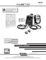
Summary of Contents for Pro-MIG 135

Page 1: ...Code Number 10889 Pro MIG 135 Sales and Service through Subsidiaries and Distributors Worldwide Cleveland Ohio 44117 1199 U S A TEL 216 481 8100 FAX 216 486 1751 WEB SITE www lincolnelectric com World...

Page 2: ...WEARERS SHOULD CONSULT WITH THEIR DOCTOR BEFORE OPERATING Read and understand the following safety highlights For additional safety information it is strongly recommended that you purchase a copy of...

Page 3: ...ical earth ground 3 f Maintain the electrode holder work clamp welding cable and welding machine in good safe operating condition Replace damaged insulation 3 g Never dip the electrode in water for co...

Page 4: ...vent the welding sparks from starting a fire Remember that welding sparks and hot materials from welding can easily go through small cracks and openings to adjacent areas Avoid welding near hydraulic...

Page 5: ...i s et non inflamma bles 4 Des gouttes de laitier en fusion sont mises de l arc de soudage Se prot ger avec des v tements de protection libres de l huile tels que les gants en cuir chemise paisse pant...

Page 6: ...e information must be followed to avoid minor personal injury or damage to this equipment CAUTION Please Examine Carton and Equipment For Damage Immediately When this equipment is shipped title passes...

Page 7: ...gs B 2 Welding Operations B 3 Overload Protection B 6 Learning to Weld B 7 Application Chart B 18 Accessories Section C Accessories C 1 Replacement Parts C 2 Maintenance Section D Safety Precautions D...

Page 8: ...L SPECIFICATIONS Pro MIG 135 INPUT SINGLE PHASE ONLY RATED OUTPUT OUTPUT RECOMMENDED INPUT CABLE AND FUSE SIZES Height Width Depth Weight 12 0 in 9 75 in 16 5 in 48 Ibs 305 mm 248 mm 419 mm 21 8 kg PH...

Page 9: ...11 MP 7 Hand shield with filter plate and lens 8 Adjustable mixed Gas Regulator Hose 9 Instructional video 10 Gasless Nozzle For available options and accessories refer to the Accessories Section of t...

Page 10: ...the louvers in the back and out the front of the unit A location that minimizes the amount of smoke and dirt drawn into the rear louvers reduces the chance of dirt accumulation that can block air pass...

Page 11: ...un conductor cable through the Gun Cable Access Hole 2 in the Pro MIG 135 case front Make sure the connector is all the way in the brass connector block Unscrew thumbscrew on the connector block a few...

Page 12: ...ith the cylinder securely installed remove the cylinder cap Stand to one side away from the out let and open the cylinder valve very slightly for an instant This blows away any dust or dirt which may...

Page 13: ...stallation meeting applicable electrical code requirements consult a qualified electrician Requirements For Rated Output A power cord with a 15 amp 125 volt three prong plug NEMA Type 5 15P is factory...

Page 14: ...wer and wanting the ease of use quality and dependability of both gas metal arc welding or GMAW also known as MIG welding and the Innershield electrode process self shielded flux cored or FCAW The Pro...

Page 15: ...mode No external shielding gas is required when used with Lincoln Innershield 035 0 9 mm NR 211 MP electrode Accommodates both 4 100 mm diameter and 8 200 mm diameter spools of wire Accepts optional S...

Page 16: ...8 200 mm diameter spool on the wire spool spindle shown in Figure B 2 To use 4 100 mm diameter spools the 2 50 mm diameter spindle must be removed See Figure B 3 Remove the wing nut and spacer at the...

Page 17: ...idle roll pressure adjustment wing nut is factory set to approximately five full turns from where the wing nut first engages the threads of the pressure arm 1 If feeding problems occur because the wi...

Page 18: ...ontact tip to work distance is about 3 8 inch 10 mm 9 To stop welding release the gun trigger and then pull the gun away from the work after the arc goes out 10 When no more welding is to be done clos...

Page 19: ...the cylinder valve closed except when using the Pro MIG 135 When finished welding a Close the cylinder valve to stop gas flow b Depress the gun trigger briefly to release the pressure in the gas hose...

Page 20: ...t current from going through an unwanted path Avoid allowing the welding circuit to pass through hinges bearings electronic components or similar devices that can be damaged See Figure B 8 Always disc...

Page 21: ...p impurities and forms the protective slag on top of the weld during cooling After running a weld bead the slag may be removed with a chipping hammer and wire brush This improves appearance and allows...

Page 22: ...ood that the metal is mild steel and that you will be able to weld the material In addition aluminum and stainless steel can be welded using the K664 1 Aluminum Welding Kit For further information on...

Page 23: ...cal up or vertical down Vertical up is used whenever a larger stronger weld is desired Vertical down is used primarily on sheet metal 5 32 3 9 mm and under for fast low penetrating welds Use of this u...

Page 24: ...to the settings suggested on the Application Guide for the welding wire and base metal thickness being used The voltage control is marked V and the wire feed speed is marked olo 4 Check that the pola...

Page 25: ...tickout ESO is the distance from the end of the contact tip to the end of the wire See Figure B 19 Once the arc has been established maintaining the correct ESO becomes extremely important The ESO sho...

Page 26: ...he work 2 Position face shield to protect face and eyes 3 Depress gun trigger hold gun so contact tip to work distance is about 3 8 to 1 2 inch 10 to 12 mm and the gun is at proper angle 4 After you s...

Page 27: ...of the four welding will be easy They are as follows 1 The Correct Welding Position Figure B 23 illustrates the correct welding position for right handed people For left handed people it is the oppos...

Page 28: ...the molten metal FIGURE B 25 Helpful Hints 1 For general welding it is not necessary to weave the arc neither forward or backward nor sideways Weld along at a steady pace You will find it easier 2 Wh...

Page 29: ...e 2 Increase drag angle 3 Decrease stickout 4 Increase WFS wire feed speed 5 Decrease travel speed 6 Check for correct gas if used To Correct Poor Penetration in order of impor tance 1 Decrease sticko...

Page 30: ...ll the gun around sharp corners 2 Keep the gun cable as straight as practical when welding 3 Do not allow dolly wheels or trucks to run over the cables 4 Keep the cable clean 5 Innershield electrode h...

Page 31: ...B 18 APPLICATION CHART B 18 Pro MIG 135...

Page 32: ...ese components due to the lubricant applied to steel wire Failure to do so may result in contaminated welds when weld ing aluminum 3 KP665 045C Drive Roll Optional Knurled drive roll for feeding 035 0...

Page 33: ...e and thread into gun and cable per Welding Wire Loading section 1 The factory installed gun liner will feed up to 035 0 9mm wire REPLACEMENT PARTS Complete Gun and Cable Assembly L8311 6 K530 4 Conta...

Page 34: ...roblems NO maintenance is required In extremely dusty locations dirt may clog the air passages causing the welder to run hot with premature tripping of ther mal protection If so blow dirt out of the w...

Page 35: ...Innershield process the gasless nozzle should be screws onto the diffuser 5 To remove gun tube from gun remove gas nozzle or gasless nozzle and remove diffuser from gun tube Remove both collars from...

Page 36: ...rm tensioner Item 2 and lift the idle roll arm Item 3 away from the drive roll Item 1 See Figure D 1 3 Turn the power switch to ON marked I 4 Set the wire speed to minimum and jog the drive unit with...

Page 37: ...nts the interchangeability of liners Once a liner has been cut for a particular gun it should not be installed in anoth er gun unless it can meet the liner cutoff length requirement Refer to Figure D...

Page 38: ...E CAUSE lists the obvious external possibilities that may contribute to the machine symptom Step 3 RECOMMENDED COURSE OF ACTION This column provides a course of action for the Possible Cause generally...

Page 39: ...SADJUSTMENT S None Contact your local Authorized Field Service Facility 1 Make sure correct voltage is applied to the machine 115vac 2 Make certain that power switch is in the ON position 3 Make sure...

Page 40: ...r or contact tip 3 Check for proper size cable liner and contact tip RECOMMENDED COURSE OF ACTION If all recommended possible areas of misadjustment have been checked and the problem persists Contact...

Page 41: ...c 2 Check for proper electrode polarity for process 3 Check gun tip for wear or dam age and proper size Replace 4 Check for proper gas and flow rate for process For MIG only 5 Check work cable for loo...

Page 42: ...SWITCH D1 D3 D2 D4 204 204 204 203 203 203 C1 59 000 f 40V 203 204 GUN CABLE CONDUCTOR BLOCK TO WORK ELECTRICAL SYMBOLS PER E1537 CAVITY NUMBERING SEQUENCE COMPONENT SIDE OF BOARD 539 541 T1 GUN TRIG...

Page 43: ...NOTES Pro MIG 135...

Page 44: ...NOTES Pro MIG 135...

Page 45: ...6 383 2259 and ask for the Welding School Registrar Lincoln Welding School BASIC COURSE 700 00 5 weeks of fundamentals There is a 10 discount on all orders of 50 00 or more for shipment at one time to...

Page 46: ...electrically live parts or electrode with skin or wet clothing Insulate yourself from work and ground No toque las partes o los electrodos bajo carga con la piel o ropa moja da Aislese del trabajo y...

Page 47: ...e Be und Entl ftung des Arbeitsplatzes Mantenha seu rosto da fuma a Use ventila o e exhaust o para remover fumo da zona respirat ria Turn power off before servicing Desconectar el cable de ali mentaci...

Page 48: ...and Service through Subsidiaries and Distributors Worldwide Cleveland Ohio 44117 1199 U S A TEL 216 481 8100 FAX 216 486 1751 WEB SITE www lincolnelectric com World s Leader in Welding and Cutting Pr...

Reviews: