


B-9
LEARNING TO WELD
B-9
Pro-MIG 135
For GMAW (MIG) Process
1. Is most of my welding performed on 16 gauge and
lighter materials?
2. Can I afford the extra expense, space, and lack of
portability required for gas cylinders and gas sup-
ply?
3. Do I require clean, finished-looking welds?
If you have answered yes to all the above questions
GMAW may be the process for you. If you have
answered no to any of the above questions, then you
should consider using the FCAW process.
For FCAW (Innershield) Process
1. Do I want simplicity and portability?
2. Will welding be performed outdoors or under windy
conditions?
3. Do I require good all position welding capability?
4. Will most welding be performed on 16 gauge and
heavier, somewhat rusty or dirty materials?
5. Weld must be cleaned prior to painting.
COMMON METALS
Most metals found around the farm, small shop or
home are low carbon steel, sometimes referred to as
mild steel. Typical items made with this type of steel
include most sheet metal, plate, pipe and rolled
shapes such as channels and angle irons. This type of
steel can usually be easily welded without special pre-
cautions. Some steels, however, contain higher car-
bon levels or other alloys and are more difficult to
weld. Basically, if a magnet sticks to the metal and
you can easily cut the metal with a file, chances are
good that the metal is mild steel and that you will be
able to weld the material. In addition, aluminum and
stainless steel can be welded using the K664-1
Aluminum Welding Kit. For further information on
identifying various types of steels and other metals,
and for proper procedures for welding them, we again
suggest you purchase a copy of
“
New Lessons in Arc
Welding
”
.
Regardless of the type of metal being welded, in order
to get a quality weld, it is important that the metal is
free of oil, paint, rust or other contaminant
’
s.
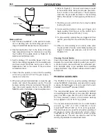
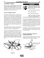
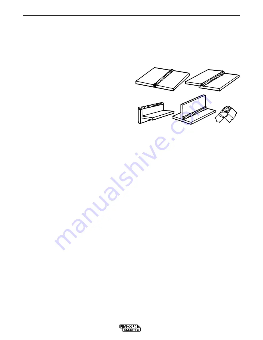
JOINT TYPES AND POSITIONS
Five types of welding joints are: Butt Welds, Fillet
Welds, Lap Welds, Edge Welds and Corner Welds.
See Figure B.11.
Of these, the Butt Weld and Fillet Weld are the two
most common welds.
FIGURE B.11
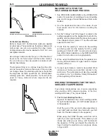
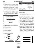
Butt Welds
Place two plates side by side, leaving a space approx-
imately one half the thickness of the metal between
them in order to get deeper penetration.
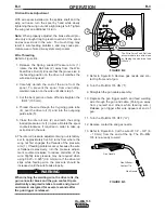
Securely clamp or tack weld the plates at both ends,
otherwise the heat will cause the plates to move apart.
See Figure B.12.
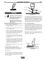
Now weld the two plates together. Weld from left to
right (if right handed). Point the wire electrode down in
the crack between the two plates, keeping the gun
slightly tilted in the direction of travel. Watch the
molten metal to be sure it distributes itself evenly on
both edges and in between the plates. This is referred
to as the
“
pull technique
”
. On thin gauge sheet metal,
use the
“
push technique
”
. See
“
Welding Techniques
for GMAW (MIG) Process
”
.
Butt weld
Lap weld
Edge weld
Fillet weld
Corner weld
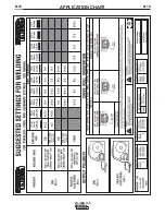
Summary of Contents for Pro-MIG 135
Page 31: ...B 18 APPLICATION CHART B 18 Pro MIG 135...
Page 43: ...NOTES Pro MIG 135...
Page 44: ...NOTES Pro MIG 135...