


Retur
n to Section TOC
Retur
n to Section TOC
Retur
n to Section TOC
Retur
n to Section TOC
Retur
n to Master TOC
Retur
n to Master TOC
Retur
n to Master TOC
Retur
n to Master TOC
INSTALLATION
PRO-CUT 60
A-5
AIR INPUT CONNECTIONS
Supply the PRO-CUT 60 with clean compressed
air or nitrogen.
•
Supply pressure must be between 70 psi
and 120 psi (482 kPa and 827 kPa).
•
Flow rate should be approximately 4.7
cfm (133 I/min.).
NOTE: Oil in the air supply to the PRO-CUT 60
can cause severe problems. Use only a clean air
supply.
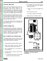
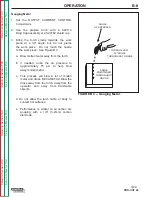
1. Connect the air supply to the PRO-CUT 60
regulator.
a. Remove the plastic thread protector from
the machine's regulator input port located
on the back of the machine. Refer to figure
A.1.
-The input port is a 1/4" (6.3mm) NPT
thread.
b. Connect the air supply to the machine reg-
ulator with an appropriate gas connection
fitting. Sealing the connection with Teflon
tape is recommended.
2. Tighten the air fitting connection to prevent
leakage.
-Do not overtighten.
NOTE: When using nitrogen gas from a cylinder,
the cylinder must have a pressure regulator.
•
Maximum psi from nitrogen gas cylinder to
PRO-CUT 60 regulator should never
exceed 120 psi (827 kPa).
•
Install a hose between the nitrogen gas
cylinder regulator and the PRO-CUT 60
regulator's gas inlet.
CYLINDER could explode if damaged.
•
Keep cylinder upright and chained to a
fixed support.
•
Keep cylinder away from areas where it
could be damaged.
•
Never lift machine with cylinder attached.
•
Never allow the cutting torch to touch the
cylinder.
•
Keep cylinder away from live electrical
parts.
•
Maximum inlet pressure 120 psi
(827kPa).
__________________
WARNING