


PRECISION TIG 185
OPERATION
B-7
B-7
Retur
n to Section TOC
Retur
n to Section TOC
Retur
n to Section TOC
Retur
n to Section TOC
Retur
n to Master TOC
Retur
n to Master TOC
Retur
n to Master TOC
Retur
n to Master TOC
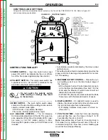
WELDING IN STICK MODE
1. Put the electrode holder and cable quick connect
plug into the electrode output receptacle. Turn clock-
wise until tight. Connect the work clamp to the work
piece.
2. Set the TIG/STICK switch to “STICK”.
3. Set the Polarity Switch to the weld mode desired for
the type of electrode being used (most commonly
DC+).
4. Place the electrode in the electrode holder.
• In Stick Mode the output terminal
and electrode will be electrically hot
whenever the power switch is turned
on.
-----------------------------------------------------------------------
5. Turn the power switch to “ON”.
6. Adjust the Current Control to the desired amps.
7. Strike an arc and weld.
NOTE:
When the TIG/STICK switch is set to “STICK”
the output is always on when the power switch is on. A
remote control has no effect on the welding current and
the gas flow and high frequency TIG arc starter are dis-
abled.
RECOMMENDED ELECTRODE AMPERAGE RANGES - PRECISION TIG 185
The PRECISION TIG 185 is rated from 5-185 Amps.
SMAW Process
Welding Amp Range for Stick Electrode Size
ELECTRODE TYPE
POLARITY
3/32"
1/8"
5/32"
Fleetweld 5P, Fleetweld 5P+ E6010
DC+
40 - 70
75 - 130
90 - 175
Fleetweld 180
E6011
DC+
40 - 80
55 - 110
105 - 135
Fleetweld 37
E6013
DC+
70 - 95
100 - 135
145 - 180
Fleetweld 47
E7014
DC-
75 - 95
100 - 145
135 - 200
Excalibur
E7018
DC+
85 - 110
110 - 160
130 - 200
Blue Max Stainless
DC+
40 - 80
75 - 110
95 - 150
Red Baron Stainless
DC+
40 - 70
60 - 100
90 - 140
Mild steel procedures are based on recommended procedures listed in C2.10 8/94 and the maximum rating of the PRECISION TIG 185
Blue Max procedures are based on C6.1 6/95
Red Baron Procedure are based on ES-503 10/93
GTAW Process
Electrode Polarity
DC-
AC
Approximate Argon
Electrode Tip Preparation
Sharpened
Balled
Gas Flow Rate
Electrode Type
EWZr
C.F.H. (l/min.)
EWTh-1, EWCe-2
EWTh-1, EWTh-2
EWTh-2, EWLa-1
EWP
EWCe-2, EWLa-1
Stainless
Tungsten Size (in.)
EWG
EWG
Aluminum
Steel
.010
Up to 15 A.
Up to 10 A.
Up to 15 A.
3-8
(2-4)
3-8
(2-4)
.020
Up to 15 A.
Up to 15 A.
Up to 20 A.
5-10
(3-5)
5-10
(3-5)
.040
Up to 80 A.
Up to 40 A.
Up to 60 A.
5-10
(3-5)
5-10
(3-5)
1/16
Up to 150 A.
Up to 100 A.
Up to 130 A.
5-10
(3-5)
9-13
(4-6)
3/32
Up to MAX. A.
Up to 160 A.
Up to MAX. A.
13-17
(6-8)
11-15 (5-7)
1/8
X
Up to MAX. A.
X
15-23 (7-11)
11-15 (5-7)
Tungsten electrodes are classified as follows by the American Welding Society (AWS):
Pure ..................................EWP ........green
TRI-MIX OF ELEMENTS.............EWG.........gray
+1% Thoria .......................EWTh-1 ...yellow
+2% Thoria .......................EWTh-2 ...red
+2% Ceria.........................EWCe-2...orange
+1.5% Lanthana ...............EWLa-1 ...black
+0.15 to 0.40% Zirconia....EWZr .......brown
Ceriated Tungsten is now widely accepted as a substitute for 2% Thoriated Tungsten in AC and DC applications.
WARNING


