Lincoln Electric INVERTEC 170TPX AUS Operator'S Manual Download Page 18

English  

English 

16

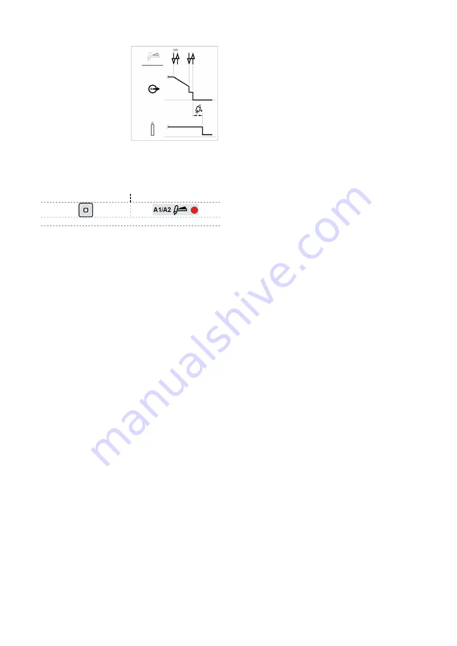
As shown here, again after 
the TIG torch trigger is 
quickly pressed and 
released from step 3A, it is 
possible to quickly press 
and release the TIG torch 
trigger a second time to 
end the downslope time 
and stop welding. 


Bi-Level (A1/A2) Trigger sequence 

The Bi-Level feature is selectable only if the “option 20” 
is previously enabled in the Setup Menu. 
 
To select Bi-Level sequence: 

Action 

Visualization


Press several times until the LED above lights up 

 
With this sequence the arc is started as in the 4S 
sequence, this means that steps 1 and 2 are the same. 


3.  Quickly press and release the TIG torch trigger.  

The machine will switch the current level from A1 to 
A2 (background current).  Each time this trigger 
action is repeated the current level will switch 
between the two levels. 

3A.    Press and hold the TIG torch trigger when 
the main part of the weld is complete.  The 
machine will now decrease the output current at 
a controlled rate, or downslope time, until the 
Crater current is reached.  This Crater current 
can be maintained as long as necessary. 

 
NOTE: The Restart option and the Pulse function are not 
available for Bi-Level Trigger sequence. 
 

Torch control functions 

Valid only for 220TPX 

The torch control functions are available if up/down 
module on the torch is assembled on torch and “Option 
50” is enabled in the Setup Menu. There are two 
functions available: 

Option 50 “Cur” change set current value

Three operating modes, corresponding to different states 
of the machine, are identified: 

  Before welding: pressing the UP or DOWN key 

causes a change of value of the Set current 

  While welding: pressing the UP or DOWN key 

causes a change of  value of the Set current during 
all phases of welding process except during the start 
functions, where the UP/DOWN function is masked. 

  Pre/post Flow: pressing the UP or DOWN key 

causes a change of value of the Set current. 

 
The change will be realized in two ways depending on 
pressed button time:  

 Step 

function 

Pressing the UP/DOWN button for a minimum time 
of 200ms and releasing it, causes the set current 
raises/falls of 1A. 

 Ramp 

function 

Pressing the UP/DOWN button for a time greaterthan 
1 sec., the set current start to increase/decrease with 

a (5A/s) ramp. If press for more then 5 ses 
increase/decrease with a ramp of (10A/s). 

The current ramp will end when the UP/DOWN button 
previously pressed is released. 
When a remote (pedal or RC-pot) device is present, 
depending on welding process selected, the UP/DOWN 
behavior is different. 
 

SMAW

In SMAW welding mode, the remote device set the 
amperage setting in the whole range, bypassing the 
main control knob in front User interface. In that case the 
signals coming from UP/DOWN 

are ignored


GTAW

In GTAW mode of welding, the remote device set the 
percentage of the main set delivered by the machine. 
Regulating the main amperage, the UP/DOWN with 
remote device will work as described above. 


Option 50 “Job” Change memory

By pressing  torch buttons user will be allowed to change 
over settings stored in memory locations from 1 to 9. 
The feature is not available during welding. 
 

Summary of Contents for INVERTEC 170TPX AUS

Page 1: ...IM2050 10 2019 REV08 INVERTEC 170TX 170TPX 220TPX OPERATOR S MANUAL ENGLISH Lincoln Electric Bester Sp z o o ul Jana III Sobieskiego 19A 58 263 Bielawa Poland www lincolnelectric eu...

Page 2: ...e Code Serial Number can be found on the machine rating plate Model Name Code Serial number Date Where Purchased ENGLISH INDEX Technical Specifications 170TX TPX CE model 1 Technical Specifications 17...

Page 3: ...ne Duty Cycle 40 C based on a 10 min period Output Current I2 Output Voltage U2 230Vac 100 Stick 110A 24 4V 100 TIG 130A 15 2V 30 Stick 160A 26 4V 35 TIG 170A 16 8V OUTPUT RANGE Welding Current Range...

Page 4: ...e 40 C based on a 10 min period Output Current I2 Output Voltage U2 230Vac 100 Stick 110A 24 4 V 100 TIG 130A 15 2 V 30 Stick 160A 26 4 V 30 TIG 170A 16 8 V 240Vac 15A circuit braker 100 Stick 75 A 23...

Page 5: ...n a 10 min period Output Current I2 Output Voltage U2 230Vac 100 Stick 130 A 25 2 V 100 TIG 150 A 16 0 V 35 Stick 170 A 27 2 V 25 TIG 220 A 18 8 V 115Vac 100 Stick 90 A 23 6 V 100 TIG 110 A 14 4 V 35...

Page 6: ...ne Radio and or television transmitters and receivers Computers or computer controlled equipment Safety and control equipment for industrial processes Equipment for calibration and measurement Persona...

Page 7: ...in or adjacent to the work area and the machine Radio and or television transmitters and receivers Computers or computer controlled equipment Safety and control equipment for industrial processes Equ...

Page 8: ...or creates electric and magnetic fields EMF EMF fields may interfere with some pacemakers and welders having a pacemaker shall consult their physician before operating this equipment CE COMPLIANCE Thi...

Page 9: ...e part to touch a gas cylinder Gas cylinders must be located away from areas where they may be subjected to physical damage or the welding process including sparks and heat sources HF CAUTION The high...

Page 10: ...e technical specification section of this manual Input Supply From Engine Driven Generators The machine is designed to operate on engine driven generators as long as the auxiliary can supply adequate...

Page 11: ...enter Green Mode Green Mode Green Mode is a feature that puts the machine in a stand by condition The output is disabled The fan is turned OFF Only the Power ON LED remains ON A moving red dash is sh...

Page 12: ...pslope Downslope ramps and Restart are disabled Spot Bi Level and 4 step functions aren t selectable Normal operation is restored when the Remote command is disconnected Thermal LED This indicator wil...

Page 13: ...welding mode this command is disabled When Pulse is active is possible to set Duty cycle Frequency Hz and Background parameters During TIG welding is not possible switch ON or OFF the Pulse command i...

Page 14: ...Voltage Press SEL Press SEL Wait 4s or start welding to store the changes Current Lift TIG GTAW welding To select Lift TIG welding Action Visualization Press MODE several times until the LED above lig...

Page 15: ...final current value after the Downslope For an explanation of the Crater operation refer to the trigger sequences explained below 7 POSTFLOW In the TIG welding modes this function controls the shield...

Page 16: ...ease the output current at a controlled rate or downslope time until the Crater current is reached and the output of the machine is turned OFF After the arc is turned OFF the gas valve will remain ope...

Page 17: ...ch trigger is quickly pressed and released from step 3A it is possible to press and hold the TIG torch trigger another time to end the downslope time and maintain the output current at the Crater curr...

Page 18: ...modes corresponding to different states of the machine are identified Before welding pressing the UP or DOWN key causes a change of value of the Set current While welding pressing the UP or DOWN key...

Page 19: ...ult valid only for 220TPX To change a setting push SEL then rotate the encoder Output Current Knob to modify the setting and push SEL again to confirm the new value Error Codes and troubleshoting If a...

Page 20: ...ected from the machine before each maintenance and service After each repair perform proper tests to ensure safety Customer Assistance Policy The business of The Lincoln Electric Company is manufactur...

Page 21: ...ue Hz Background ONLY 220 170 TPX 30 10 90 step 1 Current selected value of set current Downslope 0s 0 20s step 0 1s Current selected value s Crater 30 5 100 step 1 Current selected value of set curre...

Page 22: ...r is not listed Contact the Lincoln Electric Service Department for any code number not listed Use the illustration of assembly page and the table below to determine where the part is located for your...

Page 23: ...alve Conn 35 50 K10513 9 z TIG torch LT 9 G 110A z 4m or 8m Ergo K10513 26 z TIG torch LT 26 G 180A z 4m or 8m Ergo K10529 26 z TIG torch LTP 26 G 180A z 4m 8m or 12m Ergo K10529 26 zX TIG torch LTP 2...

Reviews: