


8
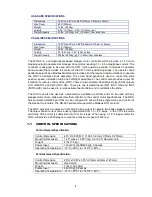
2.4 USER I/O CONTROLS
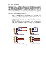
The control also provides a user I/O interface for remote control of the WOC. There are two isolated
Solid State Relay (SSR) outputs CR1 (READY) and CR2 (OSC ON). There are two Isolated inputs INP1
(OSC ON) and INP2 (INITIALIZE) can be used to remote activate the Oscillator and to reinitialize the
slide. The SSR outputs are rated at 28 VDC @ 100ma and the inputs are rated at 12 – 28 VDC @ 10
ma. The inputs and outputs provide galvanic isolation from the WOC controller. There are two separate
commons for the two inputs and outputs. The WOC also provides a non-isolated 24 VDC @ 100 ma
source that can be used to operate the WOC I/O.
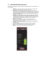
The following is a functional description of the WOC 2 I/O:
•
INP1
– When activated this “OSC ON” input will start the oscillation cycle. When
deactivated the oscillation will be stopped. If the oscillation was started with the
operator pendant then this input is ignored.
•
INP2
– When activated this input will reinitialize the slide. This input is only active when
not jogging or oscillating the slide.
•
CR1
- This “READY” output is active when the WOC controller is initialized and ready
for normal operation.
•
CR2
– This “OSC RUN” output is active when the oscillator is active. It will remain
active while the “RUN” switch or the remote INP1 is active. “OSC RUN” will remain
active until the slide has returned to the oscillation center position.
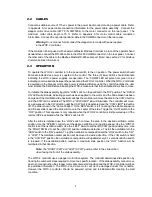
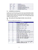
Fig 2-4: Users I/O Configuration
"INP2"
"INP1"
"+24 VDC"
"OCOM"
"PCOM"
"ICOM"
"CR1"
"CR2"
WHT
BRN
GRN
YEL
GRY
PNK
RED
BLU
GND
1
2
3
4
5
6
7
8
SHLD
J4
REMOTE I/0
TYPICAL USER INPUT CONFIGURATION
"OSC ON"
"INITIALIZE"
USER SU24
USER SUPPLIED COM
"INP2"
"INP1"
"+24 VDC"
"OCOM"
"PCOM"
"ICOM"
"CR1"
"CR2"
WHT
BRN
GRN
YEL
GRY
PNK
RED
BLU
GND
1
2
3
4
5
6
7
8
SHLD
J4
REMOTE I/0
ALTERNET USER INPUT CONFIGURATION
"OSC ON"
"INITIALIZE"
"INP2"
"INP1"
"+24 VDC"
"OCOM"
"PCOM"
"ICOM"
"CR1"
"CR2"
WHT
BRN
GRN
YEL
GRY
PNK
RED
BLU
1
2
3
4
5
6
7
8
SHLD
J4
REMOTE I/0
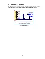
TYPICAL USER OUTPUT CONFIGURATION
GND
USER SU24 VDC
"READY" OUTPUT
"OSC ON" OUTPUT
"INP2"
"INP1"
"+24 VDC"
"OCOM"
"PCOM"
"ICOM"
"CR1"
"CR2"
WHT
BRN
GRN
YEL
GRY
PNK
RED
BLU
1
2
3
4
5
6
7
8
SHLD
J4
REMOTE I/0
TYPICAL USER OUTPUT CONFIGURATION
GND
USER INPUT COMMON
"READY" OUTPUT (+24 VDC)
"OSC ON" OUTPUT (+24)
Summary of Contents for CWT WOC-2
Page 2: ......
Page 9: ......
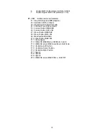
Page 32: ...23 APPENDIX A SYSTEM DRAWINGS A 1 WOC 2 Enclosure Assembly 110VAC P N S3A5171...
Page 34: ...25 A 2 WOC 2 Enclosure Assembly 220VAC P N S3A5172...
Page 36: ...27 A 3 WOC 2 Operator Pendant P N E3A5069...
Page 40: ......


