CHARGING THE BATTERY
When you charge, jump, replace, or otherwise connect battery
cables to the battery, be sure the polarity is correct. Improper
polarity can damage the charging circuit. The AIR VANTAGE®
500 positive (+) battery terminal has a red terminal cover.
If you need to charge the battery with an external charger,
disconnect the negative cable first, then the positive cable before
you attach the charger leads. After the battery is charged,
reconnect the positive battery cable first and the negative cable
last. Failure to do so can result in damage to the internal charger
components.
Follow the instructions of the battery charger manufacturer for
proper charger settings and charging time.
NAMEPLATES / WARNING DECALS
MAINTENANCE
Whenever routine maintenance is performed on this machine - or
at least yearly - inspect all nameplates and labels for legibility.
Replace those which are no longer clear. Refer to the parts list for
the replacement item number.
WELDER / GENERATOR
MAINTENANCE
STORAGE
Store the AIR VANTAGE® in a clean, dry protected areas.
CLEANING
Blow out the generator and controls periodically with low pressure
air. Do this at least once a week in particularly dirty areas.
BRUSH REMOVAL AND REPLACEMENT
It is normal for the brushes and slip rings to wear and darken
slightly. Inspect the brushes when a generator overhaul is
necessary.
Do not attempt to polish slip rings while the engine is
running.
--------------------------------------------------------------------------------------
GFCI RECEPTACLE TESTING AND RESETTING
PROCEDURE
The GFCI receptacle should be properly tested at least once
every month or whenever it is tripped. To properly test and reset
the GFCI receptacle:
• If the receptacle has tripped, first carefully remove any load and
check it for damage.
• If the equipment has been shut down, it must be restarted.
• The equipment needs to be operating at high idle speed and
any necessary adjustments made on the control panel so that
the equipment is providing at least 80 volts to the receptacle
input terminals.
• The circuit breaker for this receptacle must not be tripped.
Reset if necessary.
• Push the "Reset" button located on the GFCI receptacle. This
will assure normal GFCI operation.
• Plug a night-light (with an "ON/OFF" switch) or other product
(such as a lamp) into the GFCI receptacle and turn the product
"ON".
• Push the "Test" button located on the GFCI receptacle. The
night-light or other product should go "OFF".
• Push the "Reset" button, again. The light or other product
should go "ON" again.
If the light or other product remains "ON" when the "Test" button
is pushed, the GFCI is not working properly or has been
incorrectly installed (miswired). If your GFCI is not working
properly, contact a qualified, certified electrician who can assess
the situation, rewire the GFCI if necessary or replace the device.
Table D.1 Engine Maintenance Components
ITEM
MAKE
PART NUMBER
SERVICE INTERVAL
Air Cleaner Element
Donaldson
P822768
Replace as indicated by
Service Indicator
Fleetguard
AF25436
Oil Filer
Cummins
C6002112110
Replace every 750 hours or 3 months,
Fleetguard
LF16011
whichever is less.
Fan Belt
Cummins
C0412021749
Inspect every 1000 hours or 12 months,
whichever is less.
Fuel Strainer
Cummins
3826094
Inspect and replace monthly as
Fleetguard
FF5079
required. Replace annually.
Fuel Filter /
Fleetguard
FS19594
Replace every 500 hours or 6 months,
Water Separator
whichever is less.
.
Battery
-----
BCI GROUP 34
Inspect every 500 hours
Engine Oil Change
See Manual
-----
Change every 750 hours or 3 months,
whichever is less. Check daily.
D-4
MAINTENANCE
D-4
AIR VANTAGE® 500 CUMMINS
WARNING
Summary of Contents for AIR VANTAGE 500 CUMMINS
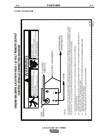
Page 37: ...F 2 DIAGRAMS F 2 AIR VANTAGE 500 CUMMINS CONNECTION DIAGRAM ...
Page 39: ...F 4 DIAGRAMS F 4 AIR VANTAGE 500 CUMMINS CONNECTION DIAGRAM ...
Page 40: ...AIR VANTAGE 500 CUMMINS F 5 DIAGRAMS F 5 CONNECTION DIAGRAM ...
Page 42: ...AIR VANTAGE 500 CUMMINS F 7 DIAGRAMS F 7 CONNECTION DIAGRAM ...
Page 43: ...AIR VANTAGE 500 CUMMINS F 8 DIAGRAMS F 8 CONNECTION DIAGRAM ...
Page 44: ...AIR VANTAGE 500 CUMMINS F 9 DIAGRAMS F 9 CONNECTION DIAGRAM ...
Page 45: ...AIR VANTAGE 500 CUMMINS F 10 DIAGRAMS F 10 CONNECTION DIAGRAM ...
Page 46: ...AIR VANTAGE 500 CUMMINS F 11 DIAGRAMS F 11 CONNECTION DIAGRAM ...
Page 47: ...AIR VANTAGE 500 CUMMINS F 12 DIAGRAMS F 12 CONNECTION DIAGRAM ...


