background image

20. CIRCUIT BREAKERS

These  circuit  breakers  provide  separate  overload  current
protection  for  each  120V  circuit  at  the  240V  single  phase
receptacle,  each  120V  single  phase  receptacle,  the  240V  three
phase  receptacle,  the  120VAC  in  the  14-Pin  connector,  the
42VAC  in  the  14-Pin  connector  and  battery  circuit  overload
protection.

21. 120VAC SINGLE PHASE RECEPTACLES

These two 120VAC (5-20R) receptacles with ground fault circuit
interruption protection provide 120VAC single phase for auxiliary
power.  Each  receptacle  has  a  20  amp  total  rating.  They  are
designed  to  protect  the  user  from  the  hazards  of  ground  faults.
When  the  GFCI  has  tripped  there  will  be  no  voltage  available
from  the  receptacle.  Refer  to  the  AUXILIARY  POWER
RECEPTACLES  section  in  the  installation  chapter  for  further
information about these receptacles. Also refer to the AUXILIARY
POWER OPERATION section later in this chapter.

22. GROUND STUD

Provides a connection point for connecting the machine case to
earth  ground.  Refer  to  “MACHINE  GROUNDING”  in  the
Installation chapter for proper machine grounding information.

23. 240VAC THREE PHASE RECEPTACLE

This  is  a  240VAC  (15-50R)  receptacle  that  provides  240VAC
three phase auxiliary power. This receptacle has a 50 amp rating.

AIR COMPRESSOR CONTROLS (24 THRU 26)

24. COMPRESSOR  ON/OFF SWITCH

Turns  compressor  on  and  off  (standby)  by  opening  and  closing
the compressor inlet valve.

25. COMPRESSOR PROTECTION LIGHT

The  yellow  compressor  protection  light  remains  off  with  proper
compressor oil temperatures. If the lights turn on, the compressor
protection  system  will  close  the  compressor  inlet  valve  and  put
the  system  in  standby  mode  until  the  temperature  reaches
allowable limits. Check for proper compressor oil level.

26. AIR DISCHARGE VALVE

Controls  flow  of  compressed  air.  A  3/4”  NPT  (National  Pipe
Thread) fitting is provided.

BATTERY JUMP START TERMINAL (27-28)

27. POSITIVE BATTERY JUMP START TERMINAL.

28. NEGATIVE BATTERY JUMP START TERMINAL.

12V battery jump start feature is standard. Covered output studs
for convenient access, and protection against accidental impact.
can  be  used  to  jump-start  a  utility  truck  with  up  to  800  cold
cranking  amps.  Can  also  be  used  to  jump-start  the  AIR
VANTAGE® 500 Cummins.

29. BATTERY DISCONNECT SWITCH

Battery  disconnect  switch  provides  lockout/tagout  capability.
Switch is conveniently located inside the engine compartment.

(SEE FIGURE B.2)

30. AIR CLEANER SERVICE INDICATOR

Air  cleaner  service  indicator  provides  a  Go/No-Go  visual
indication  of  useful  filter  service  life.  Also  located  inside  the
engine compartment. (SEE FIGURE B.2)

ENGINE OPERATION

STARTING THE ENGINE

1. Open  the  engine  compartment  door  and  check  that  the  fuel

shutoff valve located to the left of the fuel filter housing is in the
open position (lever to be in line with the hose).

2. Make sure battery disconnect switch is in the on position.

3. Check  for  proper  oil  level  and  coolant  level.  Close  engine

compartment door.

4. Remove all plugs connected to the AC power receptacles.

5. Set IDLER switch to “AUTO”.

6. Set the RUN/STOP switch to “RUN”. Observe that the engine

protection and battery charging lights are on. After 10 seconds,
the engine protection light will turn off.

7. Within  30  seconds,  press  and  hold  the  engine  START  button

until the engine starts.

8. Release the engine START button when the engine starts.

9. Check  that  the  engine  protection  and  battery  charging  lights

are  off.  The  engine  protection  light  is  on  after  starting,  the
engine  will  shutdown  in  a  few  seconds.  Investigate  any
indicated problem.

10. Allow  the  engine  to  warm  up  at  low  idle  speed  for  several

minutes before applying a load and/or switching to high idle.
Allow a longer warm up time in cold weather.

COLD WEATHER STARTING

With a fully charged battery and the proper weight oil, the engine
should  start  satisfactorily  even  down  to  about  0°F(-18°C).  If  the
engine  must  be  frequently  started  below  10°(-12°C),  it  may  be
desirable  to  install  the  optional  ether  start  kit  (K887-1).  For
extreme  cold  conditions  it  may  be  desirable  to  install  the  Cold
Weather Heater and Tarp Kit (K2359-1). Installation and operating
instructions are included in the kits.

STOPPING THE ENGINE

1. Switch  the  RUN/STOP  switch  to  “STOP”.  This  turns  off  the

voltage supplied to the shutdown solenoid. A backup shutdown
can be accomplished by shutting off the fuel valve located on
the fuel line.

FIGURE B.2

B-5

OPERATION

B-5

AIR VANTAGE® 500 CUMMINS

30

29

Summary of Contents for AIR VANTAGE 500 CUMMINS

Page 1: ...THOUT READING THIS MANUAL AND THE SAFETY PRECAUTIONS CONTAINED THROUGHOUT Most importantly think before you act and be careful OPERATOR S MANUAL Copyright Lincoln Global Inc World s Leader in Welding and Cutting Products Sales and Service through Subsidiaries and Distributors Worldwide Cleveland Ohio 44117 1199 USA Tel 216 481 8100 Fax 216 486 1751 Web Site www lincolnelectric com IM826 A For use ...

Page 2: ...tting ANSI Standard Z49 1 from the American Welding Society PO Box 351040 Miami Florida 33135 or CSA Standard W117 2 1974 or WTIA Welding Technology Institute of Australia PO Box 6165 Silverwater NSW 2128 A free copy of Arc Welding Safety booklet E205 is available from the Lincoln Electrical Company 22801 St Clair Avenue Cleveland Ohio 44117 1199 BE SURE THAT ALL INSTALLATION OPERATION MAINTENANCE...

Page 3: ... arc to keep fumes and gases away from the breathing zone When welding with electrodes which require special ventilation such as stainless or hard facing see instructions on container or MSDS or on lead or cadmium plated steel and other metals or coatings which produce highly toxic fumes keep exposure as low as possible and within applicable OSHA PEL and ACGIH TLV limits using local exhaust or mec...

Page 4: ...o adjacent areas Avoid welding near hydraulic lines Have a fire extinguisher readily available 6 b Where compressed gases are to be used at the job site special precautions should be used to prevent hazardous situations Refer to Safety in Welding and Cutting ANSI Standard Z49 1 and the operating information for the equipment being used 6 c When not welding make certain no part of the electrode cir...

Page 5: ...propriés et non inflammables 4 Des gouttes de laitier en fusion sont émises de l arc de soudage Se protéger avec des vêtements de protection libres de l huile tels que les gants en cuir chemise épaisse pantalons sans revers et chaussures montantes 5 Toujours porter des lunettes de sécurité dans la zone de soudage Utiliser des lunettes avec écrans lateraux dans les zones où l on pique le laitier 6 ...

Page 6: ...ortant when identifying the correct replacement parts On Line Product Registration Register your machine with Lincoln Electric either via fax or over the Internet For faxing Complete the form on the back of the warranty statement included in the literature packet accompanying this machine and fax the form per the instructions printed on it For On Line Registration Go to our WEB SITE at www lincoln...

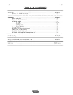
Page 7: ...Wire Feeders A 8 A 9 Operation Section B Safety Instructions B 1 General Description B 1 Recommended Applications B 1 Air Compressor B 1 Controls and Settings B 2 Engine Controls B 2 B 3 Welder Controls B 4 Auxiliary Power Controls B 4 Air Compressor Controls B 5 Battery Jump Start Terminals B 5 Engine Operation B 5 Starting the Engine B 5 Stopping the Engine B 5 Break In Period B 6 Typical Fuel C...

Page 8: ...intenance D 1 Engine Maintenance D 1 Air Filter D 1 D 2 Fuel Filters D 3 Cooling System D 3 Battery Handling D 3 Charging the Battery D 4 Nameplate Warning Decal Maintenance D 4 Welder Generator Maintenance D 4 Engine Maintenance Components D 4 GFCI Receptacle Testing and Resetting Procedure D 4 Troubleshooting Section E Wiring Connection Diagrams and Dimension Print Section F Parts Lists P 495 Se...

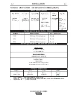
Page 9: ... 60 550 Amps DC multi purpose 36 volts 50 575 Amps DC multi purpose 35 volts PHYSICAL DIMENSIONS Height 2 Width Depth Weight 42 0 in 32 7 in 63 1 in 1690 lbs 1066 8 mm 830 1mm 1603mm 766kg Approx 1 Output rating in watts is equivalent to volt amperes at unity power factor Output voltage is within 10 at all loads up to rated capacity When welding available auxiliary power will be reduced 2 Top of E...

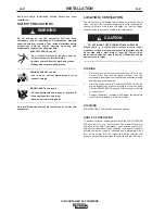
Page 10: ...here there is a combustible surface directly under stationary or fixed electrical equipment that surface should be covered with a steel plate at least 06 1 6mm thick which should extend not less than 5 90 150mm beyond the equipment on all sides STORING 1 Store the machine in a cool dry place when it is not in use Protect it from dust and dirt Keep it where it can t be accidentally damaged from con...

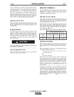
Page 11: ...y 10 C 21 F above 40 C 104 F TOWING The recommended trailer for use with this equipment for road in plant and yard towing by a vehicle 1 is Lincoln s K2636 1 If the user adapts a non Lincoln trailer he must assume responsibility that the method of attachment and usage does not result in a safety hazard nor damage the welding equipment Some of the factors to be considered are as follows 1 Design ca...

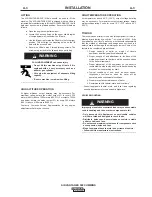
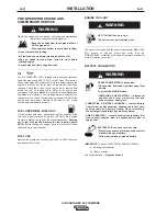
Page 12: ...ual for specific fuel recommendations Running out of fuel may require bleeding the fuel injection pump NOTE Before starting the engine open the fuel shutoff valve pointer to be in line with hose FUEL CAP Remove the plastic cap covering from the Fuel Tank Filler neck and install the Fuel Cap ENGINE COOLANT HOT COOLANT can burn skin Do not remove cap if radiator is hot The welder is shipped with the...

Page 13: ...nect to the terminals provided These connections should be checked periodically and tightened if necessary Listed in Table A 1 are copper cable sizes recommended for the rated current and duty cycle Lengths stipulated are the distance from the welder to work and back to the welder again Cable sizes are increased for greater lengths primarily for the purpose of minimizing cable voltage drop Table A...

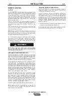
Page 14: ...er capacity of the AIR VANTAGE 500 is 12 000 watts of 60 Hz single phase or 20 000 watts of 60Hz three phase power The auxiliary power capacity rating in watts is equivalent to volt amperes at unity power factor The maximum permissible current of the 240 VAC output is 50 A The 240 VAC single phase output can be split to provide two separate 120 VAC outputs with a maximum permissible current of 50 ...

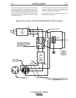
Page 15: ...uctor cable of the desired length The 50 amp 120 240 VAC plug is available in the optional K802R plug kit 4 Plug this cable into the 50 Amp 120 240 Volt receptacle on the AIR VANTAGE 500 case front Figure A 2 Connection of the AIR VANTAGE 500 to Premises Wiring 240 Volt 60 Hz 3 Wire Service POWER COMPANY METER 240 VOLT 120 VOLT 120 VOLT LOAD N NEUTRAL BUS GROUND PREMISES DISCONNECT AND SERVICE OVE...

Page 16: ...er is closed the wire will begin to feed and the welding process is started Shut the welder off For electrode Positive connect the electrode cable to the terminal of the welder and work cable to the terminal of the welder For electrode Negative connect the electrode cable terminal of the welder and work cable to the terminal of the welder Across The Arc Model Attach the single lead from the front ...

Page 17: ...nob to desired crispness Generally welding is best if the ARC CONTROL is set to SOFT for MIG and CRISP for INNERSHIELD You may however want to start in the middle and adjust as needed from there Set the IDLE switch to the AUTO position When not welding the AIR VANTAGE 500 engine will be at the low idle speed If you are using an LN 25 with an internal contactor the electrode is not energized until ...

Page 18: ...ving parts and insure proper cooling air flow GENERAL DESCRIPTION The AIR VANTAGE 500 is a diesel engine driven welding power source The machine uses a brush type alternating current generator for DC multi purpose welding for 120 240 VAC single phase and 240V three phase auxiliary standby power The AIR VANTAGE 500 also has a rotary screw 60 cfm air compressor built in The welding control system us...

Page 19: ...he ring gear and or starter motor 3 HOUR METER The hour meter displays the total time that the engine has been running This meter is a useful indicator for scheduling preventive maintenance 4 FUEL LEVEL GAUGE Displays the level of diesel fuel in the fuel tank The operator must watch the fuel level closely to prevent running out of fuel and possibly having to bleed the system 5 ENGINE TEMPERATURE G...

Page 20: ... after starting the engine the engine will operate at full speed for approximately 12 seconds and then go to low idle speed b When the electrode touches the work or power is drawn for lights or tools approximately 100 Watts minimum the engine accelerates and operates at full speed c When welding ceases and the AC power load is turned off a fixed time delay of approximately 12 seconds starts d If t...

Page 21: ... increase spatter It is recommended that the ARC CONTROL be set to the minimum number without electrode sticking Start with a setting at 0 DOWNHILL PIPE mode In this mode the ARC CONTROL knob sets the short circuit current arc force during stick welding to adjust for a soft or a more forceful digging arc Crisp Increasing the number from 10 Soft to 10 Crisp increases the short circuit current which...

Page 22: ...start a utility truck with up to 800 cold cranking amps Can also be used to jump start the AIR VANTAGE 500 Cummins 29 BATTERY DISCONNECT SWITCH Battery disconnect switch provides lockout tagout capability Switch is conveniently located inside the engine compartment SEE FIGURE B 2 30 AIR CLEANER SERVICE INDICATOR Air cleaner service indicator provides a Go No Go visual indication of useful filter s...

Page 23: ...nd cap passes where weld puddle control and deposition stacking of iron are key to fast travel speeds It is recommended that the ARC CONTROL be set initially at 0 TOUCH START TIG MODE The AIR VANTAGE 500 can be used in a wide variety of DC TIG welding applications The TOUCH START TIG setting of the MODE switch is for DC TIG Tungsten Inert Gas welding To initiate a weld the OUTPUT CONTROL knob is f...

Page 24: ... 2 1 8 250 400 25 40 7 11 15 23 5 7 11 15 4 0 5 32 400 500 40 55 10 12 21 25 6 8 13 17 8 10 4 8 3 16 500 750 55 80 11 13 23 27 8 10 18 22 6 4 1 4 750 1000 80 125 13 15 28 32 11 13 23 27 1 When used with argon gas The current ranges shown must be reduced when using argon helium or pure helium shielding gases 2 Tungsten electrodes are classified as follows by the American Welding Society AWS Pure EW...

Page 25: ...he GFCI receptacle Start the engine and set the IDLER control switch to the desired operating mode Full power is available regardless of the welding control settings if no welding current is being drawn The auxiliary power of the AIR VANTAGE 500 consists of two 20 Amp 120VAC single phase 5 20R GFCI duplex receptacles one 50 Amp 120 240VAC single phase 14 50R receptacle and one 50 Amp 240VAC three ...

Page 26: ...5 175 150 125 53 107 42 84 69 53 46 38 300 600 225 450 250 300 250 200 91 183 69 137 76 91 76 61 Maximum Allowable Cord Length in ft m for Conductor Size Conductor size is based on maximum 2 0 voltage drop 14 AWG 12 AWG 10 AWG 8 AWG 6 AWG 4 AWG TABLE B 4 AIR VANTAGE 500 SIMULTANEOUS WELDING AND POWER LOADS WELD AMPS 0 100 200 250 300 400 500 1 PHASE WATTS AMPS 12 000 50 12 000 50 12 000 50 12 000 ...

Page 27: ...unts to standard muffler K1816 1 Full KVA Adapter Kit Plugs into the 120 240V NEMA 14 50R receptacle on the case front which accepts 4 prong plugs and converts it to a NEMA 6 50R receptacle which accepts 3 prong plugs for connection to Lincoln Equipment with a NEMA 6 50P plug T12153 9 Full KVA Power Plug One dual voltage plug rated at 120 240V 50 amps single phase Pipe Thawing with an arc welder c...

Page 28: ...chine with low pressure air periodically In particularly dirty locations this may be required once a week COMPRESSOR MAINTENANCE Refer to the Routine Maintenance section of the compressor owner s manual for the recommended maintenance schedule of the following a Compressor oil and filter b Compressor air filter c Compressor coalescing filter VMAC VEHICLE MOUNTED AIR COMPRESSORS www VMAC ca 1333 Ki...

Page 29: ...o the job of seating the filter ñ but it will not Using the latches to push the filter in could cause damage to the housing and will void the warranty Donaldson filters with RadialSeal Sealing Technology are self aligning self centering and self sealing A new filter has a dry lubricant to aid installation The critical sealing area will stretch slightly adjust itself and distribute the sealing pres...

Page 30: ...ld battery first and connect to new battery last CONNECTING A BATTERY CHARGER Remove battery from welder by disconnecting negative cable first then positive cable and battery clamp When reinstalling connect negative cable last Keep well ventilated USING A BOOSTER connect positive lead to battery first then connect negative lead to engine foot BATTERY ACID CAN BURN EYES AND SKIN Wear gloves and eye...

Page 31: ...ully remove any load and check it for damage If the equipment has been shut down it must be restarted The equipment needs to be operating at high idle speed and any necessary adjustments made on the control panel so that the equipment is providing at least 80 volts to the receptacle input terminals The circuit breaker for this receptacle must not be tripped Reset if necessary Push the Reset button...

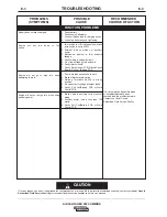
Page 32: ... Service Facility HOW TO USE TROUBLESHOOTING GUIDE Service and Repair should only be performed by Lincoln Electric Factory Trained Personnel Unauthorized repairs performed on this equipment may result in danger to the technician and machine operator and will invalidate your factory warranty For your safety and to avoid Electrical Shock please observe all safety notes and precautions detailed throu...

Page 33: ...emperature or low oil pressure engine protection light lit 1 Low oil pressure engine protection light lit Check oil level Consult engine service dealer 2 High water temperature Check engine cooling system engine protection light lit 3 Faulty oil pressure switch 4 Faulty water temperature switch Contact authorized local Engine Service Shop 1 High water temperature 1 Dirty fuel or air filters may ne...

Page 34: ...il Battery PCB 1 Poor work lead connection to work 2 Broken idler solenoid spring 3 Welding Terminals switch in wrong position 4 No open circuit voltage at output studs 5 Faulty Pull Coil Battery PCB or Weld Control PCB 1 Broken wire in auxiliary current sensor wiring 2 Auxiliary power load is less than 100 watts 3 Faulty Pull Coil Battery PCB or Weld Control PCB RECOMMENDED COURSE OF ACTION If al...

Page 35: ...trol PCB Pull Coil Battery PCB or Chopper PCB 1 GFCI Receptacle may have tripped Follow GFCI Receptacle Testing and Resetting Procedure in the MAINTENANCE section of this manual 2 Open breakers may need to be reset 3 Faulty receptacle 4 Faulty auxiliary circuit wiring 5 GFCI tripped RECOMMENDED COURSE OF ACTION If all recommended possible areas of misadjustment have been checked and the problem pe...

Page 36: ...AGE 500 CUMMINS NOTE This diagram is for reference only It may not be accurate for all machines covered by this manual The specific diagram for your particular machine is pasted inside the machine on one of the enclosure panels ...

Page 37: ...F 2 DIAGRAMS F 2 AIR VANTAGE 500 CUMMINS CONNECTION DIAGRAM ...

Page 38: ... CAUTION ANY INCREASE OF THE HIGH IDLE ENGINE RPM BY CHANGING THE GOVERNOR SETTING OR OVERRIDING THE THROTTLE LINKAGE WILL CAUSE AN INCREASE IN THE THE AC AUXILIARY VOLTAGE IF THIS VOLTAGE GOES OVER 140 VOLTS WIRE FEEDER CONTROL CIRCUITS MAY BE THE ENGINE WELDER OPERATING MANUAL N A WELDING CABLE MUST BE OF PROPER CAPACITY FOR THE CURRENT AND DUTY CYCLE OF IMMEDIATE AND FUTURE APPILICATIONS SEE OP...

Page 39: ...F 4 DIAGRAMS F 4 AIR VANTAGE 500 CUMMINS CONNECTION DIAGRAM ...

Page 40: ...AIR VANTAGE 500 CUMMINS F 5 DIAGRAMS F 5 CONNECTION DIAGRAM ...

Page 41: ...ANY INCREASE OF THE HIGH IDLE ENGINE RPM BY CHANGING THE GOVERNOR SETTING OR OVERRIDING THE THROTTLE LINKAGE WILL CAUSE AN INCREASE IN THE THE AC AUXILIARY VOLTAGE IF THIS VOLTAGE GOES OVER 140 VOLTS WIRE FEEDER CONTROL CIRCUITS MAY BE DAMAGED THE ENGINE GOVERNOR SETTING IS PRE SET AT THE FACTORY DO NOT ADJUST ABOVE RPM SPECIFICATIONS LISTED IN N B USE VOLTMETER SWITCH TO SELECT DESIRED ELECTRODE ...

Page 42: ...AIR VANTAGE 500 CUMMINS F 7 DIAGRAMS F 7 CONNECTION DIAGRAM ...

Page 43: ...AIR VANTAGE 500 CUMMINS F 8 DIAGRAMS F 8 CONNECTION DIAGRAM ...

Page 44: ...AIR VANTAGE 500 CUMMINS F 9 DIAGRAMS F 9 CONNECTION DIAGRAM ...

Page 45: ...AIR VANTAGE 500 CUMMINS F 10 DIAGRAMS F 10 CONNECTION DIAGRAM ...

Page 46: ...AIR VANTAGE 500 CUMMINS F 11 DIAGRAMS F 11 CONNECTION DIAGRAM ...

Page 47: ...AIR VANTAGE 500 CUMMINS F 12 DIAGRAMS F 12 CONNECTION DIAGRAM ...

Page 48: ...E OIL IN COMPRESSOR COOLANT IN RADIATOR AND EMPTY FUEL TANK N A 6 53 165 9 24 97 634 2 32 08 814 8 42 35 1075 7 52 52 1334 42 00 1066 8 46 35 1177 3 6 56 166 6 63 10 1602 7 9 10 231 1 36 13 917 7 48 92 1242 6 NOTE This diagram is for reference only It may not be accurate for all machines covered by this manual The specific diagram for a particular code is pasted inside the machine on one of the en...

Page 49: ...h electrically live parts or electrode with skin or wet clothing Insulate yourself from work and ground No toque las partes o los electrodos bajo carga con la piel o ropa mojada Aislese del trabajo y de la tierra Ne laissez ni la peau ni des vêtements mouillés entrer en contact avec des pièces sous tension Isolez vous du travail et de la terre Berühren Sie keine stromführenden Teile oder Elektrode...

Page 50: ... gute Be und Entlüftung des Arbeitsplatzes Mantenha seu rosto da fumaça Use ventilação e exhaustão para remover fumo da zona respiratória Turn power off before servicing Desconectar el cable de alimentación de poder de la máquina antes de iniciar cualquier servicio Débranchez le courant avant l entretien Strom vor Wartungsarbeiten abschalten Netzstrom völlig öffnen Maschine anhalten Não opere com ...

Page 51: ...d s Leader in Welding and Cutting Products Sales and Service through Subsidiaries and Distributors Worldwide Cleveland Ohio 44117 1199 USA Tel 216 481 8100 Fax 216 486 1751 Web Site www lincolnelectric com ...

Reviews: