background image

i                                                                

SAFETY                                     

i


ARC WELDING CAN BE HAZARDOUS. PROTECT YOURSELF AND OTHERS FROM POSSIBLE 

SERIOUS INJURY OR DEATH.  KEEP CHILDREN AWAY.  PACEMAKER WEARERS SHOULD 

CONSULT WITH THEIR DOCTOR BEFORE OPERATING.  


Read and understand the following safety highlights. For additional safety information, it is strongly recommended  

That  you  purchase  a  copy  of   “ Safety in  Welding &  Cutting –

 ANSI Standard 

Z49.1 ” from the American 


Welding Society, P.O. Box 351040, Miami, Florida 33135 or CSA Standard W117.2-

1974. A Free copy of “Arc Welding 


Safety ” booklet  E205  is  available  from  the Lincoln Electric Company, 22801 St. Clair Avenue, Cleveland, Ohio


44117-1199.  


BE SURE THAT ALL INSTALLATION, OPERATION, MAINTENANCE AND REPAIR PROCEDURES 

PERFORMED ONLY BY QUALIFIED INDIVIDUALS.  


1.a. Electric current flowing through any conductor causes localized Electric and Magnetic Fields  (EMF). Welding current 

          creates EMF  fields  around welding cables and welding machines. 


   1.b. EMF fields may  interfere  with  some  pacemakers, and welders having a pacemaker should consult with their physician 

          before welding. 


   1.c. Exposure to EMF fields in welding may have other health effects which are now not known.  


   1.d. All welders should use the following procedures in order to  minimize exposure  to  EMF  fields from the welding  

          circuit: 


          1.d.1. Route the electrode and work cables together. Secure them with tape when possible. 


          1.d.2. Never coil the electrode lead around your body.  


          1.d.3. Do not place your body between the electrode and work cables. If  the electrode cable is on your right side, 

                    the work cable should also be on your right side. 


          1.d.4. Connect the work cable to the workpiece as close as possible to the area being welded. 


          1.d.5. Do not work next to welding power source.  


!   

WARNING 

 ELECTRIC AND MAGNETIC FIELDS 

 May be dangerous 

Summary of Contents for 76202

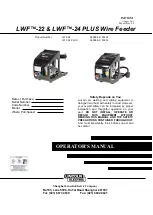
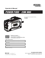
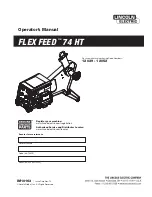
Page 1: ...e Serial Number Code Number Model Where Purchased Safety Depends on You Lincoln arc welding and cutting equipment is designed and built with safety in mind However your overall safety can be increased by proper installation and thoughtful operation on your part DO NOT INSTALL OPERATE OR REPAIR THIS EQUIPMENT WITHOUT READING THIS MANUAL AND THE SAFETY PRECAUTIONS CONTAINED THROUGHOUT And most impor...

Page 2: ...conductor causes localized Electric and Magnetic Fields EMF Welding current creates EMF fields around welding cables and welding machines 1 b EMF fields may interfere with some pacemakers and welders having a pacemaker should consult with their physician before welding 1 c Exposure to EMF fields in welding may have other health effects which are now not known 1 d All welders should use the followi...

Page 3: ...ith the proper filter and cover plates to protect your eyes from sparks and the rays of the arc welding or observing open arc welding The headshield and filter lens should conform to ANSI Z87 I standards 3 b Use suitable clothing made from durable flame resistant material to protect your skin and that of your helpers from the arc rays 3 c Protect other nearby personnel with suitable non flammable ...

Page 4: ...rk cables connected to the building framework or other locations away from the welding area increase the possibility of the welding current passing through lifting chains crane cables or other alternate circuits This can create fire hazards or overheat lifting chains or cables until they fail 6 a Use only compressed gas cylinders containing the correct shielding gas for the process used and proper...

Page 5: ...____________________ Date of Purchase ______________________ Whenever you request replacement parts for or information on this equipment always supply the Information you have recorded above Read this Operators Manual completely before attempting to use this equipment Save this manual and keep it handy for quick reference Pay particular attention to the safety instructions we have provided for you...

Page 6: ...elding Cable A 2 Gas Hose A 2 Control Cable A 2 Option Extension Cables A 2 Welding Gun A 2 Connection Diagram LWF Feeder to Lincoln OPTIMARC A 2 Operation Section B Installing Drive Rolls B 1 Loading the Wire Spool B 1 LWFTM 22 B 1 LWFTM 24 PLUS B 2 Maintenance Section C Maintenance C 1 Schematic Diagram Section D Schematic Diagram D 1 ...

Page 7: ...IDTH DEPTH WEIGHT LWFTM 22 350mm 280mm 450mm 10 5kg LWFTM 24 PLUS 350mm 280mm 450mm 12 5kg Note Please only use this wire feeder with specified power sources otherwise no output will be produced and the machine may be damaged SAFETY PRECAUTIONS Turn off the input power at the fuse box before working on other equipment connected to the welding system at the disconnect switch or fuse box before work...

Page 8: ... and blend gas can be used and the gas pressure cannot be more than 0 7 MPa CONTROL CABLE The control cable is included in the interconnection cable assembly When it is used with DURAWELD OPTIMARC the 6 pin connector on the control cable will be linked to the rear panel of wire feeder and 6 pin connector on the power source OPTION EXTENSION CABLES The LWFTM wire feeders can also be used with exten...

Page 9: ...s for feeding 1 2 1 6mm Ensure that the drive roll is installed using the correct groove for the wire diameter being used Notice make sure the specifications of the 2 symmetrical feed rolls are same And don t make any mistake about it LOADING THE WIRE SPOOL x LWF 22 Loosen the retainer on the spindle and put on the welding wire spool Next replace the retainer and tighten the screw Release the pres...

Page 10: ...nduit and V groove of feed roll then insert it into the feedplate Then insert the welding wire into V groove of another feed roll and contact tip Push down the pressure handle at last Adjust the pressure to feed wire smoothly Then using the cold inch button on the feeder begin feeding wire Release the cold inch button when the wire comes out 1 2cm 1 2 1 inch from the contact tip The installation o...

Page 11: ...feed rolls Clean the dust and powder and find out the cause x Check if the diameter of the outlet suits the wire diameter If not suitable erratic arc or powder will occur x Check if the end of the wire outlet is lined up with the V groove of the feed roll Visual inspection If they are not lined up erratic arc or powder will occur Feed Rolls x Check if the diameter of the feed roll is suitable for ...

Page 12: ...D 1 SCHEMATIC DIAGRAM D 1 ...

Page 13: ...Except for special instructions experiments on welding machines are conducted in accordance with the general standard of IEC60974 1 experiments on welding consumables are conducted in accordance with the general standard of AWS for specific applicable standards on welding consumables please refer to the product page The product performance data of this website and related attachments are from LINC...

Reviews: