


SMAX - SSI and analogue
On the contrary, with descending ramp, before the initial position of the travel
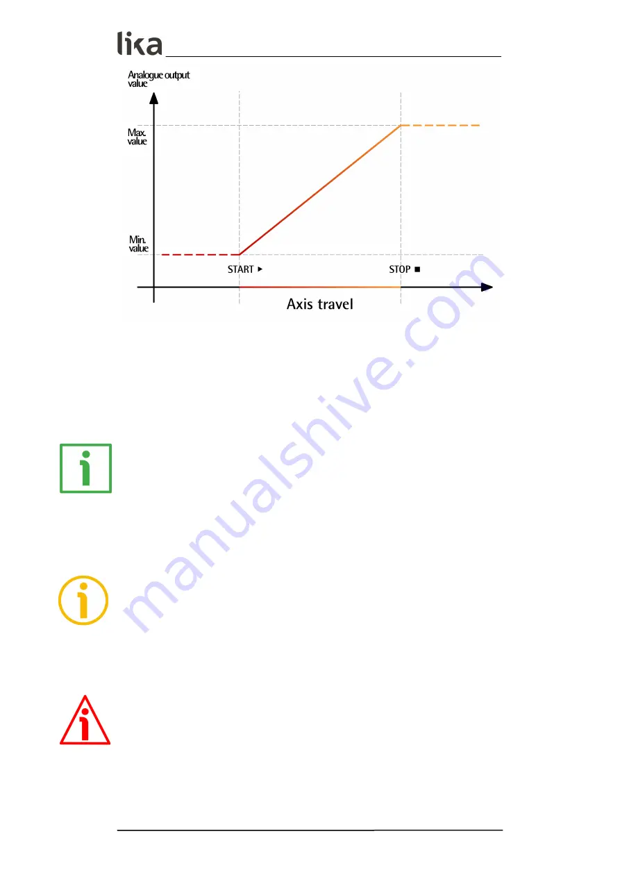
the encoder will provide the maximum current / voltage signal level of the
output range (20 mA for SMAX-AI1-...; 10 V for SMAX-AV2-...); after the last
position of the travel the encoder will provide the minimum current / voltage
signal level of the output range (4 mA for SMAX-AI1-...; 0 V for SMAX-AV2-...).
So for instance, if you have a SMAX-AV2-... sensor (its output range is 0-10 V)
and you program an ascending ramp, then the encoder will provide a fixed
voltage level of 0 V for the positions before the origin of the travel (i.e. the point
where you activate the
START
input); a voltage level increasing from 0 V
(origin of the travel, position 0) to 10 V (end of the travel) for the 1024 positions
of the axis; a fixed voltage level of 10 V for the positions after the last point of
the travel (i.e. the point where you activate the
STOP
input).
NOTE
For any further information on the
START
and
STOP
input signals refer to
the “5.2 Signals description” section on page 21.
5.3.1 TEACH-IN procedure
WARNING
It is mandatory to activate the
START
input first and then the
STOP
input.
To programme the encoder using the TEACH-IN procedure act as follows. The
steps to define a ramp with increasing output values are described hereinafter;
MAN SMAX SSI_AI1_AV2 E 1.5.odt
5 - Analogue interface
25 of 32