Through-‐Zero VCO Manual 0.1
7
Connecting to a CV Source
The main tuning CV can be connected either through the front panel
jacks (the 1-v/Oct input is preferred) or via the 16-pin header on the
back of the module.
The other CV inputs have an exponential control relationship and can
be used to, for example, add an offset to the VCO tuning when
multiple VCO’s are played together. This can be particularly effective
with a sequencer where a repeating pattern can be transposed to a
different frequency each time the pattern is repeated.
VCO Outputs
The VCO module provides all the usual waveforms – Sine, Triangle,
Saw, Square and Pulse. In addition to these there are half-frequency
square and double-frequency saw outputs that extend the range of
the oscillator by two octaves. Each output is 10V
p-p
with a 1k output
impedance.
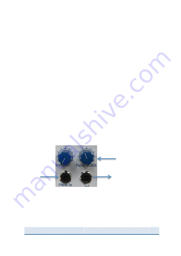
Pulse-‐Width Modulation
The pulse output can be varied both manually and by an external
modulation source. When an external source is used the ‘Pulse
Width’ control sets the point that the output is modulated around so
that quite subtle PWM effects can be achieved.
Linear FM
The linear FM input is AC coupled with a cut-off frequency of 3Hz, to
ensure that modulation signals connected to this input will not
detune the VCO.
Initial Pulse Width
Pulse Output
Pulse-Width
Modulation
Input