background image

10 


WARRANTY REGISTRATION 


Please  visit  the  following  link  to  complete  the  product  warranty  form  online.  Please  visit 

http://warrantyform.lifespanfitness.com.au/ 


PLEASE  NOTE:  YOUR  WARRANTY  IS  ONLY  VALID  IF  YOU  CAN 

PROVE YOU ARE THE ORIGINAL PURCHASER ON THIS ITEM (i.e. A copy of the receipt, 
invoice, delivery date or internet confirmation


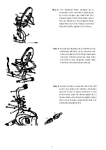
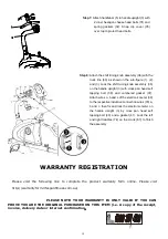
Step 8:

 Attach the shift tuning knob assembly (36) with the 

truck line (80) as shown in the sub-figure (1), (2) 
and (3). Lock the shift tuning knob assembly (36) 
on the handle upright (3) with cross pan head self 
tapping  bolt  (38)  and  cambered  gasket  (37). 
Attach wires a, b and c of the electronic meter (39) 
to the respective inductive connection wires (79) a, 
b and c, then fix and lock the electronic meter on 
the  handle  upright  (3)  by  cross  pan  head  self 
tapping bolt (40) and a gasket (41). Lock the left 
and right treadles (74) on the crank (67) to finish 
the assembly. 

Step 7:

 Attach handlebar (5) to handle upright (3) with 

2-inner hexagon cheese head bolts (31) and 
spring  gaskets  (32).  Snap  clip  cover  (35) 
over top to protect head bolts. 


Summary of Contents for RC 80

Page 1: ...RC 80 Owner s Manual ...

Page 2: ...ntinuing with your exercise program 4 Keep children and pets away from the equipment The equipment is designed for adult use only 5 Use the equipment on a solid flat level surface with a protective cover for your floor or carpet To ensure safety the equipment should have at least 1 65 feet of free space around it 6 Before using the equipment check that the nuts and bolts are securely tightened 7 T...

Page 3: ......

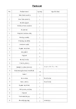
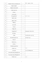
Page 4: ...nt leg assembly 1 9 Armrest assembly 1 10 Square neck bolt 4 11 Arc gasket 4 12 Cap nut 4 13 Rear leg end cap 2 14 Front leg end cap 2 15 Inductive connection wire 2 Length 850 15a 15b 16 Inner hexagon cheese head bolt 16 17 Gasket 11 18 Seat cushion 1 Vinyl bottom 19 Back cushion 1 Vinyl bottom 20 Square neck bolt 2 21 Wire passing vent plug 1 22 Cap nut 2 23 Seat handlebar grip 2 24 Round pipe p...

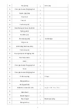
Page 5: ...lded pipe 35 Clip cover 1 36 shift tuning knob assembly 1 37 Cambered gasket 1 38 Cross pan head self tapping bolt 1 39 Electronic meter 1 40 Gasket 4 41 Cross pan head self tapping bolt 4 42 Sensor 1 43 Cross pan head self tapping bolt 2 44 Tension spring 1 16 loops 45 Hexagonal nut 2 46 Hexagonal bolt 1 47 Inductive connection wire 2 Length 1100 47a 47b 48 Idler wheel 1 49 Round magnet 1 50 Pipe...

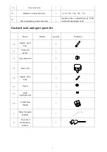
Page 6: ...61 Bearing 2 62 Adjust bolt 2 63 Thin nut 2 64 Flange nut 2 65 Triangle belt 1 Manufacturer Sanwei 864 66 Belt pulley 1 67 Crank 1 left and right reverse teeth 68 Bottom bracket cup 2 Nine piece type 69 Ball rack 2 70 Shaft sleeve 2 71 Gasket 2 72 Crank hexagonal nut 1 73 Crank cover 1 7 2D 74 Foot pedal 1 L R with binding band 75 Cross pan head self tapping bolt 4 76 Cross pan head self tapping b...

Page 7: ...cting bolt 1300 with a thrum length of 42 Enclosed tools and spare parts list Name Model Quantity Thumbnail 10 Square neck bolt 4 11 Cambered gasket 4 12 Cap shaped nut 4 28 Elastic bolt 1 20 Square neck bolt 2 21 Gasket 2 22 High cap shaped nut 2 36 8 shift fine tuning 1 A Inner hexagon spanner 1 B Cross head multipurpose spanner 1 ...

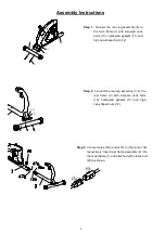
Page 8: ...bered gaskets 11 and high cap shaped nuts 12 Step 3 Connect wires 47a and 47b to 15a and 15b respectively Insert rear frame assembly 2 into the main frame 1 and attached with elastic bolt 28 as shown Step 1 Connect the rear leg assembly 8 to the main frame 1 with 2 square neck bolts 10 cambered gaskets 11 and high cap shaped nuts 12 ...

Page 9: ...e backboard frame assembly 4 is connected to the rear frame assembly 2 by 4 inner hexagon pan head bolts 16 The seat cushion 18 and the back cushion 19 are attached to the backboard frame respectively by 4 inner hexagon pan head bolts 16 and the gaskets 17 as shown Step 5 The armrest assembly 9 is attached to the backboard assembly 4 by 2 square neck bolts 20 gaskets 17 and high cap shaped nuts 22...

Page 10: ... the sub figure 1 2 and 3 Lock the shift tuning knob assembly 36 on the handle upright 3 with cross pan head self tapping bolt 38 and cambered gasket 37 Attach wires a b and c of the electronic meter 39 to the respective inductive connection wires 79 a b and c then fix and lock the electronic meter on the handle upright 3 by cross pan head self tapping bolt 40 and a gasket 41 Lock the left and rig...

Reviews: