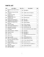
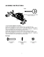
LifeGear 93772 KNIGHT Owner'S Manual Download Page 6


5

PARTS LIST


No. Description Qty No.

Description Qty

054 

Rear Decorate Cover for Front 

Post 

1 076 Bolt 

M8x25 

055 

Hand Pulse Sensor with Wire 

L=750mm 

2  077  M10x1.0 Nut for Flywheel 

056 

Handrail Foam Grip 

Ø31xØ37x480   

2 078 Flywheel 

Ø230x40x32 

057 

Handlebar Foam Grip 

Ø21xØ27x360   

2 079 Belt 

PJ400 

J6 

058  Handrail End Cap Ø32x1.5 

2  080  Idler Arm 

059  Handlebar End Cap Ø28x1.5 

2  081  Bolt M6x15 

060 

Phillips Self Tapping Screw 

ST4.2x25 

6 082 Eyebolt 

M6x36 

061 Screw 

ST4.8x20 

3 083 Tension 

Bracket 

062  Curve Washer Ø28xØ17x0.3 

1  084  Hexagon Nut M6 

063  Adjustable Leveler M10 

2  085  Spring Washer Ø6 

064 

Extension Sensor Wire 

L=1100mm 

1  086  Powder Metal Bushing Ø18xØ8x5

065  Sensor with Wire L=1600mm 

1  087  Nut M10 

066 Screw 

ST2.9x12 

2 088 Bolt 

M5x10 

067 Left 

Cover  

1 089 Bolt 

M6x15 

068  Right Cover   

1  090 

Front Decorate Cover for Front 

Post 

069  Bearing 6003Z 

2  091  Left Decorate Cover   

070  M10x1.25 Nut for Flywheel 

2  092  Right Decorate Cover 

071 

Extension Hand Pulse Sensor 

Wire L=300mm 

2  093  Curve Washer Ø16xØ8 

072 Screw 

ST4.2x15 

16 094 Screw 

ST4.2x12 

073 

Phillips Self Tapping Screw 

ST4.2x20 

8  095  Round Shaped Cap Ø38x14.5 

074  Plastic Post Ø8x32 

2  096  Washer Ø11xØ10x1 

075  Belt Pulley Ø260 

1   


Summary of Contents for 93772 KNIGHT

Page 1: ...72 OWNER S MANUAL IMPORTANT Read all instructions carefully before using this product Retain this owner s manual for future reference The specifications of this product may vary from this photo subjec...

Page 2: ...2 IMPORTANT SAFETY INSTRUCTIONS 3 PARTS LIST 4 HARDWARE PACKING LIST 6 TOOLS 6 OVERVIEW DRAWING 7 ASSEMBLY INSTRUCTIONS 8 OPERATING THE COMPUTER 15 ADJUSTMENTS 18 MAINTENANCE 19 TROUBLESHOOTING 19 WAR...

Page 3: ...repairing free of charge any parts which may prove to be defective under normal home use This warranty does not include any damage caused by improper operation misuse or commercial application From t...

Page 4: ...al When using please hold the handlebar by hands make the pedals running smoothly by push or pull handlebars then run the equipment regularly by cooperation of hands and feet After exercise please als...

Page 5: ...r 40 2 010L Front Left Stabilizer End Cap 60 1 038 Bolt M8x15 8 010R Front Right Stabilizer End Cap 60 1 039 Powder Metal Bushing 14 2x 10 2x10 4 011 Big Curve Washer 20x 8 10 040 Bolt M8x20 4 012 Cap...

Page 6: ...ve Washer 28x 17x0 3 1 084 Hexagon Nut M6 2 063 Adjustable Leveler M10 2 085 Spring Washer 6 6 064 Extension Sensor Wire L 1100mm 1 086 Powder Metal Bushing 18x 8x5 4 065 Sensor with Wire L 1600mm 1 0...

Page 7: ...ver S10 S13 S14 S15 1 PC 9 Bolt M8x70 4 PCS 11 Big Curve Washer 20x 8 4 PCS 12 Cap Nut M8 4 PCS 24 Nylon Nut M6 10 PCS 25 Washer 6 6 PCS 26 Bolt M6x40 6 PCS 28 Cap S13 2 PCS 44 Bolt M6x35 4 PCS 45 Cur...

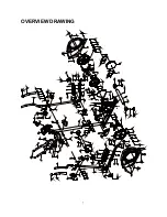
Page 8: ...7 OVERVIEW DRAWING...

Page 9: ...nuts with the Multi Hex Tool with Phillips Screwdriver provided Position the Rear Stabilizer 8 behind the Main Frame 1 and align bolt holes Attach the Rear Stabilizer 8 onto the rear curve of the Main...

Page 10: ...see Figure B Insert the metal fitting on the resistance cable of Tension Control Knob 51 into the hole at the end of the slot in the metal bracket of Tension Cable 27 see Figure C Connect the resistan...

Page 11: ...at were removed Tighten bolt with the S6 Allen Wrench provided Remove one M8x20 Bolt 40 one 38x14 5 Round Shaped Cap 95 and 38x3 D Shaped Washer 42 from the left Crank 13 Remove bolt with the S6 Allen...

Page 12: ...ighten screws with the Multi Hex Tool with Phillips Screwdriver provided Repeat above step to attach the Right Handrail Arm 3R onto the right horizontal axis of the Front Post 5 and right U Shape Brac...

Page 13: ...rail Arms 3L 3R with four M6x35 Bolts 44 four 6 Curve Washers 45 and four M6 Nylon Nuts 24 Tighten nylon nuts with the Multi Hex Tool with Phillips Screwdriver provided Hardware 24 Nylon Nut M6 4 PCS...

Page 14: ...ST4 2x20 Phillips Self Tapping Screws 73 from the Right Handrail Arm 3R Remove screws with the Multi Hex Tool with Phillips Screwdriver provided Attach the Right Handrail Arm Cover A 50R and Right Han...

Page 15: ...shers 93 that were removed Tighten bolts with the S6 Allen Wrench provided Remove four M5x10 Bolts 88 from the back of the Computer 53 Remove bolts with the Multi Hex Tool with Phillips Screwdriver pr...

Page 16: ...press the MODE button to confirm the month The date will begin blinking press the SET button to change the date and press the MODE button to confirm the date After set up is done the computer will dis...

Page 17: ...tion per Minute The split window of SPEED and RPM will display SPEED and RPM alternately every 5 seconds DISTANCE Displays the accumulative distance traveled during workout You may also pre set target...

Page 18: ...ss the RESET button to clear the target heart rate to zero The pre set heart rate range is from 72 to 240 beats per minute Once you pre set target heart rate and then start to exercise please grip the...

Page 19: ...control knob in a clockwise direction To decrease the tension turn the tension control knob in a counterclockwise direction Adjusting the Adjustable Leveler Turn the adjustable leveler on the rear st...

Page 20: ...r There is no display on the computer console 1 Remove the computer console and verify the wires that come from the computer console are properly connected to the wires that come from the front post 2...

Page 21: ...state at the end of each exercise session A proper cool down slowly lowers your heart rate and allows blood to return to the heart HEAD ROLLS Rotate your head to the right for one count you should fee...

Page 22: ...ean against a wall with your left leg in front of the right and your arms forward Keep your right leg straight and the left foot on the floor then bend the left leg and lean forward by moving your hip...

Reviews: