background image


6

ASSEMBLY INSTRUCTIONS   


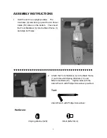
1.  Hold the unit in an upright position.  The 

Controller (9) side facing up and the AC Power 

Cable (16) side is on the bottom.    Then insert 

the Front Stabilizer (3) into the Main Frame (1) 

and align bolt holes. 


․․․․․․․․․․․․․․․․․․․․․․․․․․․․․․․․․․․․․․․․


2.  Attach the Front Stabilizer (3) to the Main Frame 

(1) with three M8 Spring Washers (13) and 

M8x16mm Bolts (14).    Tighten bolts with the   

Allen Wrench with Phillips Screwdriver provided. 


Tool: 

Allen Wrench with Phillips Screwdriver 

Hardware: 

3 Spring Washer (M8) 

3 Bolt (M8x16mm) 

Summary of Contents for 16062

Page 1: ...Motorized Oxy Cycle Item No 16062 Owner s Manual The specifications of this product may vary from this photo and are subject to change without notice 2010 Jan ...

Page 2: ...d under the conditions that it has been installed and operated in accordance with LifeGear s Owner s Manual LifeGear s obligation under this warranty is limited to replacing or repairing free of charge any parts which may prove to be defective under normal home use This warranty does not include any damage caused by improper operation misuse or commercial application From the date of purchase the ...

Page 3: ...ycle as directed in Assembly Instructions and place unit on a level non slip surface 9 Keep hands and feet away from any moving parts Do not insert any object into any openings 10 Perform 3 to 5 minutes of warm up and stretching before beginning your exercise 11 Never exercise to exhaustion 12 Do not stand on the motorized oxy cycle only exercise in seated position 13 Keep a minimum safety clearan...

Page 4: ...disabled persons 4 Use the motorized oxy cycle only for its intended use as described in this manual Do not use attachments not recommended by the manufacturer 5 Never operate the motorized oxy cycle if it has a damaged cord or plug If it is not working properly if it has been dropped or damaged or dropped into water 6 Do not carry the motorized oxy cycle by supply cord or use cord as a handle 7 K...

Page 5: ...4 OVERVIEW DRAWING 1 2 3 4 4 5L 5R 6 8 9 10 11 12 13 14 14 13 14 14 15L 15R 7 16 17R 18 17L 18 10 10 10 10 19 20 22 21 23 4 4 24 ...

Page 6: ...rank 1 005L Left Cover 1 017L Left Crank 1 006 Digital Display Computer 1 018 Plastic Cap 2 007 Power Control Board 1 019 Bolt M4x5mm 2 008 Motor 1 020 Bolt M6x12mm 6 009 Controller 1 021 Spring Washer M6 6 010 Screw ST4x16mm 14 022 PCB Support 5 011 Controller Bracket 1 023 Round Magnet 1 012 Square Sensor 1 024 Non Slip Mat 1 013 Spring Washer M8 6 HARDWARE PACKING LIST TOOLS 13 Spring Washer M8...

Page 7: ...Then insert the Front Stabilizer 3 into the Main Frame 1 and align bolt holes 2 Attach the Front Stabilizer 3 to the Main Frame 1 with three M8 Spring Washers 13 and M8x16mm Bolts 14 Tighten bolts with the Allen Wrench with Phillips Screwdriver provided 2 1 Tool Allen Wrench with Phillips Screwdriver Hardware 3 Spring Washer M8 3 Bolt M8x16mm ...

Page 8: ...holes 4 Attach the Rear Stabilizer 2 to the Main Frame 1 with three M8 Spring Washers 13 and M8x16mm Bolts 14 Tighten bolts with the Allen Wrench with Phillips Screwdriver provided 3 4 Tool Allen Wrench with Phillips Screwdriver Hardware 3 Spring Washer M8 3 Bolt M8x16mm ...

Page 9: ...ten pedal shaft of Right Foot Pedal 15R with the Multi Hex Tool provided Note The Cranks Foot Pedals and Pedal Shafts are marked R for Right and L for Left Foot Pedal Strap Adjustment Snap the three hole end of the pedal strap onto the inside edge of the Left Foot Pedal 15L Snap the other end of the pedal strap onto the outside edge of the Left Pedal 15L Select adjustment holes which allow your fo...

Page 10: ...urrent training speed in kilometers per hour DIS DISTANCE Displays the accumulative distance traveled during exercise CAL CALORIES Displays the calories burned during exercise ODO ODOMETER Displays the total accumulative distance traveled RPM REVOLUTIONS PER MINUTE Displays the current RPM STOP The unit is stopped AUTO START Start motion or push button AUTO DISPLAY SHUT OFF After approximately 4 m...

Page 11: ...KNOB is turned to OFF position before plug the power cord into the electrical outlet To disconnect turn the SPEED CONTROL KNOB to the OFF position then remove plug from the electrical outlet STORAGE PRECAUTIONS Do not store the motorized oxy cycle in any place where it will be subjected to high or low temperature Do not expose to direct sunlight or outdoor for extended periods of time Do not store...

Page 12: ... the increase level of strength and endurance 5 Always start your exercise slowly to warm up muscles 6 The design of the motorized oxy cycle allows you to exercise your muscles with movements that are natural and efficient The Overload Principal In order for you to strengthen your body you must develop a series of exercise workouts each day When you work out on a regular basis your body specifical...

Page 13: ...e Speed Control Knob in a clockwise direction to start exercise again Range of motion and flexibility This motorized oxy cycle can be used both upper and lower body As a lower body device it works with passive motion to increase tone of the quadriceps muscles muscles in the thigh and circulate blood flow to the entire lower leg and foot For upper body use it perform as a resistance device allowing...

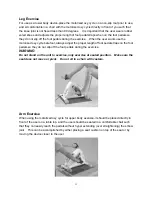
Page 14: ...t always adjust the proper length of foot pedal straps on the foot pedals so they do not slip off the foot pedals during the exercise WARNING Do not stand on the unit to exercise only exercise at seated position Make sure the seat does not move or pivot Do not sit in a chair with casters Arm Exercise When using the motorized oxy cycle for upper body exercise it should be placed directly in front o...

Reviews: