background image

Page


|


6


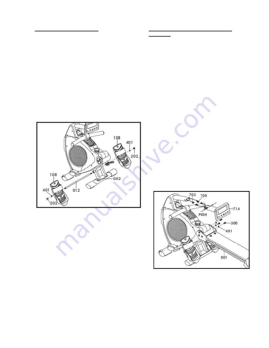
Step 10: Aluminum Beam & Computer 
Assembly 
 
Tools Needed: 

5mm Allen wrench 
 

Note: Additional assistance may be needed. Make 
sure the wires are connected together properly. 
Push and store excess wires back into main frame. 
Be careful not to pinch the wires while assembling 
the console 


A. Using the provided 5mm Allen wrench, remove 

the preassembled Qty. six bolts (300) and Qty. 
six washers (401) from the die cast pivot (004). 
 

B. Slide the aluminum beam (001) onto the die 

cast pivot (004) 

Note: Additional assistance me 

be needed to help align the holes.

 Firmly 

secure the Qty. six bolts (300) and Qty. six 
washers (401) in place with the provided 5mm 
Allen wrench.  

 
C. Locate  the computer  console (714) and make 

sure that wires (703 & 705) are connected 
together properly with the computer cables

.


D. Gently press in the pop pins on the sides of the 

computer arm (150) and slide the arm into main 
assembly.  


E.  Discard and recycle the packaging material 

and read the manual thoroughly before using 
the rower.  


Congratulations! 

Assembly for the R99 rower is complete. 

Step 9: Foot Pedal Assembly 
 
Tools Needed: 

13mm wrenches 


A. Locate the foot pedal bar (012) and remove the 

preassembled Qty. two nuts (202) and Qty. two 
washers (401). Slide the foot pedal bar through 
the main frame (002) as shown in the diagram 
below. 
 

B. Locate the left and right foot pedals (108) and 

slide them onto the foot pedal bar (012). With 
the previously removed Qty. two nuts (202) and 
Qty. two washers (401) secure them to the foot 
pedal bar. Using the provided 13mm wrenches, 
firmly tighten the nuts (202).  


Summary of Contents for LC-R99

Page 1: ...User s Product Manual LifeCore LC R99 Rower...

Page 2: ...eCORE the best it can be please review the enclosed user s manual prior to assembly and first use Be sure to keep the instructions for reference and or maintenance We also offer a complete line of fit...

Page 3: ...Contents Safety Instructions and Warnings Assembly Instructions Setting Up Your Rower Correct Rowing Guide Console Operation Instructions Calculating Target Heart Rate Heart Rate Monitoring Device Ca...

Page 4: ...pment on a solid level surface when in use 11 Place your unit in an area with enough clearance to operate the equipment 12 Make sure all components are fastened securely at all times Product Safety In...

Page 5: ...Needed 5mm Allen wrench A Locate the aluminum beam 001 and place it upside down on top of the carton lid as shown in the diagram below B With the provided 5mm Allen wrench remove the preassembled Qty...

Page 6: ...Place the handlebar in the holder C Tilt the main frame 002 back so that the front of the machine is in the air Remove the preassembled Qty two bolts 305 and Qty 2 washers 405 with the 14mm wrench D...

Page 7: ...mputer console 714 and make sure that wires 703 705 are connected together properly with the computer cables D Gently press in the pop pins on the sides of the computer arm 150 and slide the arm into...

Page 8: ...of the machine Note Never mix old and new batteries and never mix different brand of batteries Never use an adaptor that isn t recommended for the rower If unit is going to be stored for a long period...

Page 9: ...25 counter clockwise five to seven turns 2 Lifting the Beam Position one hand on the aluminum beam 001 while the other hand pulls down on the clamp to release the safety lock This will allow the alumi...

Page 10: ...now move the machine to the desired location After the move gently set the machine down at its new location WARNING Never attempt to move the R99 by yourself ask for additional help if needed and neve...

Page 11: ...pivot the computer to the desired height and angle Note For safety reasons while exercising avoid the drive strap from touching the computer Air Vent Adjustment The rower s flywheel fan generates an a...

Page 12: ...pedals also pivot to allow the feet to move with rowing 1 Loosen the Velcro straps and adjust your feet accordingly Pull on the strap to tighten the strap around your feet Secure the Velcro down as s...

Page 13: ...Pull the pull strap towards the middle of the body The wrists are flat and the elbows are pulled back towards the body Locking The Knees Fault At the end of the stroke the user locks the knees making...

Page 14: ...ss any button or pull on the pull strap to activate console When a power source is plugged into the machine it will prompt you to set the current time and date The information will be stored in the co...

Page 15: ...dial to adjust the value and press the ENTER key to confirm the value Note Setting a number other than 0 in those display windows will count the number down If data display setting is set at 0 the rea...

Page 16: ...t a fitness score Note A heart rate pulse has to be read before and during for this function to work Press the RECOVERY key after a workout the time display will start counting down from 60 seconds an...

Page 17: ...the console or press hold the RESET key for a couple of seconds the console will enter user profile selection mode In user profile selection mode dot matrix window will show U0 U1 U4 Rotate the SELEC...

Page 18: ...selection is complete 2 Choose Time If the time value is not a goal you would like to set press the ENTER key to skip to the next value A default 00 00 min will display in the data display window and...

Page 19: ...ss the START STOP key and begin to row The preset value will count down and all other data will register or count up until the preset value is reached C Programs Preset Profile Programs When the SELEC...

Page 20: ...console will automatically adjust the resistance level during the program time according to your speed to maintain your watt goal When the SELECT dial is rotated during category selection mode WATTS...

Page 21: ...here are 4 H R C programs T H R 90 75 55 During H R C program selection a heart rate goal indicator graphic will light up to show which H R C program is selected Press the ENTER key to confirm the hea...

Page 22: ...5 5 59 5 37 5 17 4 59 4 43 4 29 4 16 4 05 SPM 23 24 25 26 27 28 29 30 31 TIME 500M 3 54 3 44 3 35 3 27 3 19 3 12 3 05 2 59 2 53 SPM 32 33 34 35 36 37 38 39 40 TIME 500M 2 48 2 43 2 38 2 34 2 29 2 25 2...

Page 23: ...per minute We recommend taking your heart rate at these times at rest after warming up during your workout and two minutes into your cool down to accurately track your progress as it relates to better...

Page 24: ...er away from your chest and moisten the conductive electrode strips located next to the buckles with water Note The transmitter is on automatically when it is being worn It is off when it is not conne...

Page 25: ...light soap water mixture followed by a dry towel You can also use a light house hold cleaner such as Windex to remove dirt and sweat The purpose of cleaning the unit is to remove body sweat from the...

Page 26: ...Page 25...

Page 27: ...Page 26...

Page 28: ...ifeCORE or an authorized LifeCORE service provider This Limited Warranty is void if the Product serial number has been defaced or removed Should any Product be submitted for warranty service be found...

Page 29: ...frames and parts replaced under this warranty will at the time of service become the property of LifeCORE LifeCORE reserves the right to change manufacturers of any parts to cover any existing warrant...

Page 30: ...omer Service Toll Free 888 815 5559 Mon Friday 7 30 5 30 PT Service lifecorefitness com Lifecore Fitness Inc 2575 Pioneer Ave Suite 101 Vista CA 92081 Visit our website for assembly videos www lifecor...

Reviews: