44
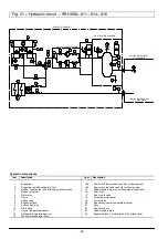
Fig. 21 ---Hydraulic circuit --- SRH 008---011---014---016
11
1
7
4
8
9
10
13
12
4
6
6
5
5
17
17
2
16
3
15
20
19
F
4
4
10
10
18
22
22
21
23
23
23
23
24
T
T
T
T
CHILLED WATER INLET
2
1
/
2
” GAS MALE
ONLY WITH PUMP VERSION
ONLY WITH TANK VERSION
CHILLED WATER OUTLET
2
1
/
2
” GAS MALE
LIEBERT--- HIROSS UNIT
F
14a
14b
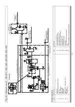
Hydraulic components
Item
Description
Item
Description
1
2
3
4
5
6
7
8
9
10
11
12
13
Evaporator
Evaporator antifreeze heater
(Opt.)
Rubber flexible pipe
(only with pumps and/or tank))
Manual air valve
Gate valve
Pump
Safety valve
Expansion tank
Service ball valve
Drain valve
Control temperature sensor
Antifreeze temperature sensor
Tank antifreeze heater
(Opt.)
14a
14b
15
16
17
18
19
20
21
22
23
24
Flow switch
(unit without tank, Opt. without pumps)
Flow switch
(unit with tank, Opt. without pumps)
Rubber flexible pipe
(only with pumps, without tank)
Filter
(Opt.)
Non---return valve
Air temperature sensor
3---way valve
Freecooling control temperature sensor
Fans
Freecooling coil
Rubber flexible pipe
Expansion tank + Safety valve
(Opt. without tank)


