Fuses
Check the continuity of the fuse. With power OFF,
pull the fuse out of the fuse block. With the ohm-
meter on the R X 1 scale, measure resistance. A
reading of infinity indicates a blown fuse and must
be replaced. Replace fuse with same type, voltage
and amp rating.
Indicator Lights
If defective, replace all indicator pilot lights with
same type.
Magnetic Contactor
Contacts
- Check the contacts for severely burnt
or welded contacts. The contactor arm should
move freely.
Coil
- Measure the coil by disconnecting one of
the coil leads. Measure the coil resistance by set-
ting the ohmmeter on the R X 1 scale. A defective
coil will read zero or infinity, indicating a short or
opened coil respectively. Replace defective con-
tactor with same type.
NOTE:
Readings may vary depending on accuracy
of the measuring device.
Motor Protective Switch
Test by inserting a paper clip or other small device
into the test hole and push to the left. The relay
should trip.
Alarm Horn
Moving the alarm test/normal/silence switch to the
test position or activating the alarm float should
turn on the alarm horn. If the horn does not sound
replace with horn of same type.
Alarm Light
Moving the alarm test/normal/silence switch to the
test position or activating the alarm float should
turn on the alarm light. If the light does not activate,
replace with bulb of same type.
Float Controls
Check the floats during their entire range of opera
-
tion. Clean, adjust, or replace floats.
Checking the float resistance
- The float resis
-
tance can be measured to determine if the float
is operating correctly or is defective. Use the fol-
lowing procedure to measure the float resistance:
1.
Isolate the float by disconnecting one or both
of the float leads from the float terminals.
2.
Place one ohmmeter lead on one of the float
wires, and the other ohmmeter lead on the
other float wire.
3.
Place the ohmmeter dial to read ohms and
place on the R X 1 scale. With the float in the
“off” position, the scale should read infinity
(high resistance). Replace the float if you do
not get this reading. With the float in the ON
position, the scale should read nearly zero
(very low resistance). Replace the float if you
do not get this reading.
NOTE:
Readings may vary depending on the
length of wire and accuracy of the measuring
device.
Troubleshooting
Installation of Floats
Standard three phase simplex panels are designed
to operate with three floats. These floats operate the
pump stop, pump start, and high level alarm functions.
NOTE: Options ordered may affect the number
of floats and their functions. Please reference
the schematic provided with the control panel for
proper installation.
CAUTION:
If control switch cables are not wired and
mounted in the correct order, the pump system will not
function properly.
WARNING:
Turn off all power before installing floats in
pump chamber. Failure to do so could result in serious
or fatal electrical shock.
1.
Use float label kit to identify and label cables on
both the float and stripped ends (stop, start, alarm,
etc.). See schematic for float options.
2.
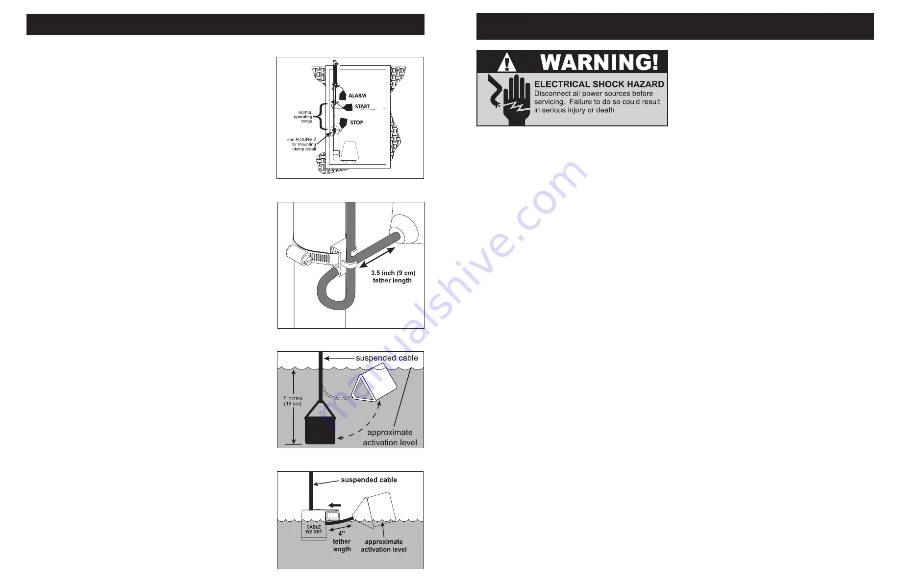
Determine your normal operating level, as illustrated
in
Figure 1
.
3.
Mount float switches at appropriate levels as il
-
lustrated in
Figures 2-4
. Be sure that floats have
free range of motion without touching each other
or other equipment in the basin.
If using the mounting clamp; follow steps 4-6.
4.
Place the cord into the clamp as shown in
Figure
2
.
5.
Locate the clamp at the desired activation level and
secure the clamp to the discharge pipe as shown
in
Figure 2
.
NOTE:
Do not install cord under hose clamp.
6.
Tighten the hose clamp using a screwdriver. Over
tightening may result in damage to the plastic
clamp. Make sure the float cable is not allowed to
touch the excess hose clamp band during operation.
NOTE:
All hose clamp components are made
of 18-8 stainless steel material. See your SJE-
Rhombus
®
supplier for replacements.
Installation Instructions
FIGURE 4:
Float with cable weight
FIGURE 1:
Three float simplex -
pump down installation
FIGURE 2
: Mounting clamp detail
FIGURE 3:
Internally weighted float
- 2 -
- 5 -
7227000B
7227000B


