background image

DL-AS61U-H2 Installation Guide

7

Installation Instructions

Mount the Matrix

Rack Mounting Instructions

At least 2 inches of free air space is required on both sides of the DL-AS61U-H2 for proper side ventilation. Avoid 

mounting the DL-AS61U-H2 near a power amplifier or any other source of significant heat.

Remove the four screws on both sides of the DL-AS61U-H2, then attach the supplied mounting clips to the       

DL-AS61U-H2 for surface or rack mounting..

Connect Sources

Connect Displays

Connect source devices to the HDMI, Display Port or VGA inputs. When using HDMI cables for source inputs, 

use a High Speed HDMI cable that is less than or equal to 1.5 meters in length for 4k60 signals and 5 meters for 

1080p signals. For source devices that are further away, it is highly recommended to install an HDMI extender 

such as the Digitalinx DL-HD70, DL-HDE100, DL-HDE100-H2 or the DL-HD2100.

When connecting a source device to the USB-C input using a USB-C cable, be sure the USB-C cable is capable of 

supporting video and is no longer than 2 meters (6.6’) in total length. The DL-AS61U-H2 USB-C input supports 

ALT-DP mode for video, to ensure a laptop is compatible with the DL-AS61U-H2 check the laptops capability of 

supporting this mode.

Note that not all laptops will support video (ALT-DP)�

Connect the display device to the HDMI output using a High Speed HDMI cable that is less than or equal to 1.5 

meters in length for 4k60 signals and 5 meters for 1080p signals. For display device that is further away, it is 

highly recommended to install an HDMI extender such as the Digitalinx DL-HD70, DL-HDE100, DL-HDE100-H2 

or the DL-HD2100.

Summary of Contents for Digitalinx DL-AS61U-H2

Page 1: ...Rev 190122 Phone 719 260 0061 Toll Free 800 530 8998 Fax 719 260 0075 DL AS61U H2 Owners Manual 11675 Ridgeline Drive Colorado Springs CO 80921 ...

Page 2: ...RATUS Use the mains plug to disconnect the apparatus from the mains THE MAINS PLUG OF THE POWER CORD MUST REMAIN READILY ACCESSIBLE Do not defeat the safety purpose polarized or grounding type plug A polarized plug has two blades with one wider than the other A grounding type plug has two blades and a third grounding prong The wide blade or the third prong is provided for your safety If the provid...

Page 3: ...trol Optional 9 Router Connection 9 Crossover Cable Connection 9 Web Browser Control 9 Applying Power 10 A V Diagram 11 Web Browser Control System Settings 12 Switcher Control 12 Connecting to Web Control Interface 12 Audio Video Switching 13 Display Control 14 VGA Output Resolution 15 Audio ON OFF Control 16 Testing RS232 17 Interface Input Names 18 Access Settings 19 Network Settings 20 EDID Man...

Page 4: ... or analog audio for audio reinforcement purposes which is de embedded from the HDMI output The switchers functions can be controlled by built in web server GUI IR remote RS232 IP or by front panel button operation Integrated CEC support for display control via front panel buttons is built in When in auto switch mode the switcher will switch to an input as soon as a new source is connected When th...

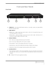
Page 5: ...nds to enable disable audio switch mode 3 DISPLAY CONTROL ON Press to turn display ON either by CEC or RS232 OFF Press to turn display OFF either by CEC or RS232 Volume Mute Press to mute display either by CEC or RS232 Volume Down Press to turn display volume down either by CEC or RS232 Volume Up Press to turn display volume up either by CEC or RS232 4 VGA RESOLUTION VGA resolution selection Press...

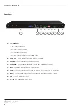
Page 6: ...r connecting to TV display 3 OPTICAL Toslink output for digital audio output 4 L R AUDIO 5 pin phoenix balanced left and right analog audio output 5 EDID Dip switch setting for EDID management 6 IR IN 3 5mm connector to connect IR receiver to control switcher by IR remote 7 RS232 3 pin phoenix output port for connection display or 3rd party control 8 TCP IP RJ45 Networking port 9 DC 24V Locking po...

Page 7: ...signals For source devices that are further away it is highly recommended to install an HDMI extender such as the Digitalinx DL HD70 DL HDE100 DL HDE100 H2 or the DL HD2100 When connecting a source device to the USB C input using a USB C cable be sure the USB C cable is capable of supporting video and is no longer than 2 meters 6 6 in total length The DL AS61U H2 USB C input supports ALT DP mode f...

Page 8: ...L AS61U H2 the switcher features a left and right balanced audio output and a digital TOSLINK output Connect Audio Optional Connect a control system to the DL AS61U H2 via RS232 for switcher control Connect RS232 Control Optional RS232 Wiring Connect the system controller RX signal to TX on the DL AS61U H2 then connect the controllers TX signal to RX on the DL AS61U H2 RS232 Settings 9600 baud 8 D...

Page 9: ...s 192 168 0 1 2 Connect the computer to the router 3 Connect the DL AS61U H2 to the router Crossover Cable Connection 1 Configure the computer to use the same network prefix as the IP address assigned to the matrix For example the IP address of the matrix is 192 168 0 178 Set the computer to use a static IP address within the same network range such as 192 168 0 42 2 Connect the network crossover ...

Page 10: ...DL AS61U H2 Installation Guide 10 Connect the included power supply to the DL AS61U H2 and lock the power supply to the power connector by twisting the locking collar clockwise Applying Power ...

Page 11: ...DL AS61U H2 Installation Guide 11 A V Diagram Display Laptop HDMI Laptop USB C Laptop DP Legacy PC BYOD Apple TV Audio System IR Remote Control System HDMI VGA A DP CAT AUDIO RS232 IR USB ...

Page 12: ... type in IP address of the DL AS61U H2 The default IP address is 192 168 0 178 Be sure the computer you are using to connect to the DL AS61U H2 is in the same IP range The login screen will appear The default user name and password is admin Switcher Control Connecting to Web Control Interface ...

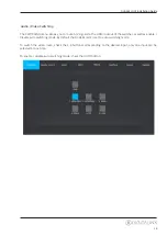
Page 13: ...tcher as well as enable disable auto switching mode By default the DL AS61U H2 is set to auto switching mode To switch the video route check the 1 6 buttons corresponding to the desired input only one input can be selected at one time To enable disable auto switching mode check the AUTO button Audio Video Switching ...

Page 14: ...le TV display is used CEC settings for displays must also be turned ON consult the TV displays owners manual on how to engage or turn ON CEC control NOTE Not all CEC compatible displays will be compatible with volume control it is a best practice to test the displays CEC compatibility with the DL AS61U H2 first before deploying into an application Use the ON OFF MUTE VOLUME VOLUME to control the d...

Page 15: ... AS61U H2 Installation Guide 15 To adjust the VGA output resolution click on the VGA RESOLUTION tab in the Display Control Menu Then choose the desired resolution then click Confirm VGA Output Resolution ...

Page 16: ...click Apply If EDID table fails the switcher will default to 1080p To use the GUI EDID feature in this tab you must select all 4 EDID dip switches on the back of the DL AS61U H2 to the ON 1 position for all pre defined options in the EDID menu above To use the User Defined EDID options in the GUI you must adjust the EDID dip switches to the following positions for their respective option User Defi...

Page 17: ...to RS232 output choose the desired Baud Rate setting choose the desired Command Ending terminator then enter the command string under the Command field Then click Send to test the command To test HEX formatted commands use the following syntax format XX XX XX XX XX hex character Example the display ON command you are testing is 0xA1 0xA2 0xA3 0xA4 0xA5 enter in A1 A2 A3 A4 A5 into the Command fiel...

Page 18: ...put names as well as assign a title to GUI control To add a title to the GUI control enter in the desired name under Title Bar Label then click Confirm to save To add user defined names to the video inputs enter in the name for each input then click Confirm to save Interface Input Names ...

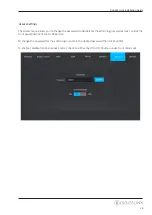
Page 19: ... for the admin login as well as lock unlock the front panel buttons of the DL AS61U H2 To change the password for the admin login enter in the desired password then click Confirm To enable disable front panel lock control check on either the ON or OFF button under Front Panel Lock Access Settings ...

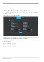
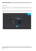
Page 20: ...Static mode with a pre defined IP address of 192 168 0 178 subnet 255 255 255 0 and gateway set to 192 168 0 1 Check either the DHCP or Static mode to change IP modes If using a Static IP address enter in the IP address subnet and gateway Then click Confirm You will need to reboot the switch for the new network settings to take place Network Settings ...

Page 21: ...gs When in the down position the switch represents 0 of OFF when the switch position in the up position it represents 1 or ON Note When using EDID copy if EDID fails the EDID will default to 1080p EDID Setting Position 1 Position 2 Position 3 Position 4 EDID Copy default 0 0 0 0 1080p 60Hz RGB 4 4 4 8bit Stereo Audio 0 0 0 1 1080p 60Hz RGB 4 4 4 8bit Multi channel Audio 0 0 1 0 1080p 60Hz RGB 4 4 ...

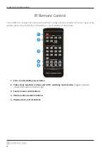
Page 22: ...panel of the switcher When using the remote control locally i e pointed directly at the switcher 1 Enter or exit standby power button 2 Video input selection buttons and AUTO switching mode button toggles between enable and disable auto switching 3 Source device control buttons 4 VGA resolution selection buttons 5 Display device control buttons ...

Page 23: ...ill not respond to switching commands in auto switching mode Description Command Examples Switch to HDMI input 1 HDMI1 Command HDMI1 Response HDMI OUT SWITCH TO 1 CR LF Switch to HDMI input 2 HDMI2 Command HDMI2 Response HDMI OUT SWITCH TO 2 CR LF Switch to HDMI input 3 HDMI3 Command HDMI1 Response HDMI OUT SWITCH TO 4 CR LF Switch to HDMI input 4 USB C input HDMI4 Command HDMI4 Response HDMI OUT ...

Page 24: ...ON CR LF Turns the TOSLINK digial audio output OFF SPDIFOFF Command SPDIFOFF Response SPDIF OUT OFF CR LF Audio Control NOTE By default the audio de embedded outputs follow the video route Below are commands you can use to breakaway audio so it can be separated and routed independently from video Description Command Examples Enable auto switching mode HDMIA Command HDMIA Response HDMI OUT SWITCH T...

Page 25: ...ponse CEC TV VOLUME DECREASE CR LF Mutes unmutes audio TVMUTE Command TVMUTE Response CEC TV VOLUME MUTE UNMUTE CR LF CEC Display Control The following commands can be used to control the display connected to the HDMI output of the DL AS61U H2 via CEC To use this feature a CEC compatible TV display must be used and the feature must be turned ON in the display menu properties NOTE Not all CEC displ...

Page 26: ... LF Restores the matrix to factory defaults RST Command RST Response FACTORY DEFAULT SCU61E VERSION V1 0 0 POWER ON FRONT PANEL UNLOCK HDMI OUT SWITCH TO AUTO MODE HDMI OUT SWITCH TO 1 DIP0000 DIP EDID0000 SPDIF OUT ON IIS OUT ON Front panel button LOCK LOCK Command LOCK Response FRONT PANEL LOCKED CR LF Front panel button UNLOCK UNLOCK Command UNLOCK Response FRONT PANEL UNLOCK CR LF System Comma...

Page 27: ...nd DTS HD Master Audio pass through DisplayPort Audio Format 8 channels LPCM up to 24bit 192Khz AC3 DTS Toslink Output PCM Dolby Digital DTS DTS HD Audio Output Balanced Stereo Analog Audio Output Connector Analog output 5 pin Phoenix Digital output Optical Toslink Audio Output Impedance 70 Ohms Frequency Response 20Hz 20KHz Control Control Port Connector 1 3 Pin Phoenix for RS232 1 RJ45 for TCP I...

Page 28: ...Thank you for your purchase For Technical Support please call our toll free number at 800 530 8998 or email us at supportlibav libav com www libav com Digitalinx is a brand of ...

Reviews: