background image

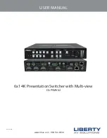
USER MANUAL / DL-PSMV62

3

Important Safety Instructions


»

Please completely read and verify you understand all instructions in this manual before operating this equipment. 


»

Keep these instructions in a safe, accessible place for future reference. 


»

Heed all warnings. 


»

Follow all instructions. 


»

Do not use this apparatus near water. 


»

Clean only with a dry cloth. 


»

Do not install near any heat sources such as radiators, heat registers, stoves, or other apparatus (including amplifiers) 

that produce heat. 


»

Use only accessories specified or recommended by Intelix.


»

Explanation of graphical symbols: 

◊  Lightning bolt/flash symbol: the lightning bolt/flash and arrowhead within an equilateral triangle 

symbol is intended to alert the user to the presence of uninsulated “dangerous voltage” within the 

product enclosure which may be of sufficient magnitude to constitute a risk of shock to a person or 

persons. 

◊  Exclamation point symbol: the exclamation point within an equilateral triangle symbol is intended 

to alert the user to the presence of important operating and maintenance (servicing) instructions 

in the literature accompanying the product. 


»

WARNING: TO REDUCE THE RISK OF FIRE OR ELECTRIC SHOCK, DO NOT EXPOSE THIS APPARATUS TO RAIN OR 

MOISTURE AND OBJECTS FILLED WITH LIQUIDS, SUCH AS VASES, SHOULD NOT BE PLACED ON THIS APPARATUS.


»

Use the mains plug to disconnect the apparatus from the mains. 


»

THE MAINS PLUG OF THE POWER CORD MUST REMAIN READILY ACCESSIBLE. 


»

Do not defeat the safety purpose polarized or grounding-type plug. A polarized plug has two blades with one wider 

than the other. A grounding-type plug has two blades and a third grounding prong. The wide blade or the third prong 

is provided for your safety. If the provided plug does not fit into your outlet, consult an electrician for replacement of 

your obsolete outlet. 

Caution! To reduce the risk of electrical shock, grounding of the center pin of this plug must be 

maintained. 


»

Protect the power cord from being walked on or pinched particularly at the plugs, convenience receptacles, and the 

point where they exit from the apparatus. 


»

Do not block the air ventilation openings. Only mount the equipment per Intelix’s instructions. 


»

Use only with the cart, stand, table, or rack specified by Intelix or sold with the equipment. When/if a 

cart is used, use caution when moving the cart/equipment combination to avoid injury from tip-over. 


»

Unplug this apparatus during lightning storms or when unused for long periods of time. 


»

Caution!

 Shock Hazard. Do not open the unit. 


»

Refer to qualified service personnel. Servicing is required when the apparatus has been damaged in any way, such as 

power supply cord or plug is damaged, liquid has been spilled or objects have fallen into the apparatus, the apparatus 

has been exposed to rain or moisture, does not operate normally, or has been dropped.  

Summary of Contents for DL-PSMV62

Page 1: ...www libav com 800 530 8998 USER MANUAL 6x1 4K Presentation Switcher with Multi view DL PSMV62 Rev 220109 ...

Page 2: ...view Mode Selection 16 Full Screen Mode Selection 16 Swap Setting 17 Window Size Setting 17 Audio Control 18 IR Remote Control 19 Web GUI Control System Settings 20 Connecting to Web GUI 20 Switching 21 Multi view Configuration 24 Auto Display Control 27 Output Resolution 28 CEC Control 29 EDID 31 Network Settings 33 Multi view Layout Naming 34 Security 35 RS232 Communication 36 RS232 and TCP IP C...

Page 3: ...TUS Use the mains plug to disconnect the apparatus from the mains THE MAINS PLUG OF THE POWER CORD MUST REMAIN READILY ACCESSIBLE Do not defeat the safety purpose polarized or grounding type plug A polarized plug has two blades with one wider than the other A grounding type plug has two blades and a third grounding prong The wide blade or the third prong is provided for your safety If the provided...

Page 4: ...USER MANUAL DL PSMV62 4 ...

Page 5: ...4k 30Hz 1080P signal up to 40 meters 131ft 70 meters 230ft all over a single CATx cable The switcher features external line audio input that can be embedded into any HDMI input and provides microphone input for voice lift The presentation switcher provides multi view functionality and supports up to 20 layouts The switcher features a wide range of control flexibility via TCP IP front panel buttons...

Page 6: ...ctors 5 SWAP Cycle swaps the video source of the multi view window display counter clockwise 6 MULTIVIEW Multi view mode toggles through 4 preset multi view layouts 7 SELECT FULL SCREENS A B Four buttons for window selection and full screen setting 8 RESIZE Adjusts the windows size 9 AUDIO SOURCE Select the audio source and the corresponding LED 1 4 will illuminate blue When LINE audio is selected...

Page 7: ...witch as needed ON for Condenser microphone OFF for Dynamic microphone 4 AUDIO OUT L R Balanced analog audio ouput for audio de embedding SPDIF Digital SPDIF audio output for audio de embedding 5 CONTROL CONTACT IN Contact external sensors buttons and other devices for input source selection IR IN Connects to IR receiver for IR pass through IR OUT Connects to IR emitter for IR pass through IR EYE ...

Page 8: ...nnect Sources Connect source devices to the HDMI Display Port or USB C inputs When using HDMI cables for source inputs use a High Speed HDMI cable that is less than or equal to 1 5 meters in length for 4k60 signals and 5 meters for 1080p signals When connecting a source device to the USB C input using a USB C cable be sure the USB C cable is a USB 3 2 Gen1 cable capable of supporting video and is ...

Page 9: ...0p signals Note The HDBaseT transmitter supports up to 40m 132 for 4K 30Hz 4 4 4 8 bit color signals up to 10Gbps and 70m 232 for 1080p signals using CAT6 F UTP cable HDBaseT Output Twisted Pair Wiring Use TIA EIA 568B wiring for Category 6 connection between send and receive units To ensure proper performance of the DL PSMV62 it is recommended that you use solid core shielded Category 6 F UTP cab...

Page 10: ...n when using condenser microphones that require phantom power Connect an unbalanced line level audio source to the switchers LINE input with the following TRS 3 5 pin out Select MIC for dynamic microphones Select 48V for condenser microphones XLR POSITIVE NEGATIVE GROUND NOTE The MIC audio input may be balanced using and input or unbalanced using input for signal and connecting input to G and sign...

Page 11: ...ll as digital audio outputs via SPDIF Connect an audio amplifier to the audio output of the DL PSMV62 the switcher features a left and right balanced audio output and a digital SPDIF output NOTE The AUDIO OUT may be balanced using and input or unbalanced using input for signal and connecting input to G and signal source ground ...

Page 12: ...To activate simply short the associated terminal to the ground terminal Connect a control system to the DL PSMV62 via RS232 for switcher control Connecting Control RS232 Wiring Connect the system controller RX signal to TX on the DL PSMV62 then connect the controllers TX signal to RX on the DL PSMV62 RS232 Settings 9600 baud 8 Data Bits 1 Stop Bit Parity none DL PSMV62 RS232 Port Connected RS232 D...

Page 13: ... cable between to the switcher and a router with a straight through cable or between the matrix and a computer with a crossover cable Web Browser Control The DL PSMV62 includes a web portal to allow control of the matrix via a standard web browser The IP address is the same address that is used for TCP IP control Connecting IR Control Use only the supplied IR receiver or emitter to the switcher fo...

Page 14: ...USER MANUAL DL PSMV62 14 Connect the included power supply to the DL PSMV62 power port connect the IEC power cord connected to power supply to a power source Applying Power ...

Page 15: ...UT button Full Screen Mode Signal Switching When in multi view mode and using a multi view layout see Multi View Mode Selection you can manually assign inputs 1 4 to the A D windows in the layout To do so press an INPUT button The input LED illuminates blue the windows A D LEDs flash Then press the desired window button A D All window LEDs besides selected window LEDs will go out then the selected...

Page 16: ...LEDs A D illuminate blue Press FULL SCREEN A D button to select the corresponding window to display in full screenmode Thecorrespondinginputsource button LED and FULL SCREEN button LED will illuminate blue other window buttons and previous multi view mode button LED goes out When switching to two window A B mode the corresponding mode LED will illuminate blue and window A and B LEDs will illuminat...

Page 17: ...ockwise fashion the SWAP LED illuminates once the button is pressed once Below is an example when the SWAP button is pressed repeatably The window A B C D size can be adjusted by repeatedly pressing the RESIZE button the button LED illuminates once when press its button once Swap Setting Window Size Setting ...

Page 18: ...view mode the output audio is from the 1 HDMI input The audio source can be changed by pressing the SOURCE button Press the volume knob to select microphone or source audio control Rotate the knob to increase or decrease the volume of the selected audio Press and hold the knob at least 3 seconds to mute the selected audio rotate the knob to unmute ...

Page 19: ... RES button for output resolution selection 3 SELECT FULL SCREEN A D buttons for output window selection and full screen setting 4 MULTIVIEW Four buttons for built in multiview mode selection and four buttons for user defined mode selection The user defined multiview modes can be set via GUI 5 AUDIO SOURCE Four buttons for audio source selection 6 VOLUME Microphone audio Mute volume up and volume ...

Page 20: ...n a web browser and type in IP address of the DL PSMV62 The default IP address is 192 168 0 178 Be sure the computer you are using to connect to the DL PSMV62 is in the same IP range to access the web GUI server The login screen will appear The default user name and password is admin Connecting to Web GUI ...

Page 21: ... menu Control 2 Click Video sub menu 3 The source selection buttons Auto button and full screen window A D buttons operate the same as the buttons of front panel buttons See Front Panel Control for reference Switching Video Control 1 3 2 ...

Page 22: ... 22 1 2 3 4 Display Control 1 Click the menu Control 2 Click Display sub menu 3 Click On or Off for Display control 4 Type command in this box to be send to control the display device and then click Send Switching Continued ...

Page 23: ...ol 2 Click Audio sub menu 3 Select audio source for both audio HDMI and HDBaseT outputs 4 Set the delay time of audio output to 0 150ms 5 Turn on or off the microphone input 6 Volume bar volume up volume down and mute buttons for microphone audio control Switching Continued ...

Page 24: ...lick Confirm 5 RESIZE Click the button to adjust the window size in a layout Note that only Layout 2 Layout 5 Layout 8 and Layout 9 Layout 12 can be adjusted 6 SWAP Click the button to cycle swap the video source of window display in counter clockwise fashion Multi view Configuration Pre defined Layout 1 3 2 4 5 6 ...

Page 25: ...USER MANUAL DL PSMV62 25 7 Click the menu Settings COG 8 Choose what inputs you will use for the multi view windows in the layout 9 Click Confirm Pre defined Layout Continued 8 7 9 ...

Page 26: ...r defined sub menu 3 Choose a layout number 4 Enter in the pixel starting and end position for each window 5 Choose what inputs you will use for the multi view windows in the layout 6 Click Confirm Multi view Configuration Continued User defined Layout 1 3 2 4 5 6 ...

Page 27: ...6 Choose command terminator NULL CR LF or CR LF then click Save 7 Type RS232 command to turn ON display device then click Save 8 Set the delay time in seconds between the Display On and Display Input Select commands 9 Enter RS232 command to turn OFF display device and then click Save Select x2 to send the command twice 10 Set the delay time of sending the Display Off command again and then click S...

Page 28: ...1 Click the menu Resolution 2 Select the output resolution for HDMI and HDBaseT outputs Select Auto for Rx to have the output resolution sync to compatible resolution of connected display 3 Click Confirm Output Resolution 1 3 2 ...

Page 29: ...USER MANUAL DL PSMV62 29 CEC Control 1 Click the menu CEC 2 Click Source sub menu 3 Choose an input 4 Click the desired function Source Control 1 2 3 4 ...

Page 30: ...USER MANUAL DL PSMV62 30 1 Click the menu CEC 2 Click Display sub menu 3 Choose an output 4 Click the desired function Display Control 1 2 3 4 CEC Control Continued ...

Page 31: ...USER MANUAL DL PSMV62 31 Pre defined EDID Setting 1 Click the menu EDID 2 Choose Setting 3 Select an input 4 Choose an EDID configuration 5 Click Confirm EDID 1 3 4 5 2 ...

Page 32: ...USER MANUAL DL PSMV62 32 User defined EDID Setting 1 Click the menu EDID 2 Choose Upload 3 Select an input 4 Choose an EDID bin file configuration from PC 5 Click Apply 1 3 4 2 EDID Continued ...

Page 33: ...ANUAL DL PSMV62 33 1 Click the menu Network 2 Choose from DHCP or Static IP mode 3 If entering in a Static IP enter in the IP address subnet mask and gateway manually 4 Click Confirm Network Settings 1 3 4 2 ...

Page 34: ...USER MANUAL DL PSMV62 34 1 Click the menu Tags 2 Choose a name for the various layouts 3 Click Confirm Multi view Layout Naming 1 3 2 ...

Page 35: ...USER MANUAL DL PSMV62 35 1 Click the menu Security 2 Choose a password then click Confirm 3 Enable Front Panel Lock if desired Security 1 3 2 ...

Page 36: ...ory Default to set switcher back to factory settings Note The baud rate listed here changes the baud rate of the switcher and passes any command besides a DL PSMV62 switcher API command through to the HDBaseT RS232 output The baud rate of the switcher and the receiver will need to always be the same RS232 Communication 1 3 2 ...

Page 37: ...ng commands below the switcher must be in manual switching mode only System will not respond to switching commands in auto switching mode Description Command Examples Enables disables auto switching mode SetAutoSwitch s s EN Enable Dis Disable Command SetAutoSwitch EN cr lf Response AutoSwitch True Queries current switch mode GetAutoSwitch Command GetAutoSwitch cr lf Response AutoSwitch True Switc...

Page 38: ... lf Response AudioSource 2 Change source volume level SetSourceVOL v v 0 60 Command SetSourceVOL 6 cr lf Response SourceVOL 6 Queries current source volume level GetSourceVOL Command GetSourceVOL cr lf Response SourceVOL 6 Mutes unmutes source audio SetSourceAudioMute m m EN Enable Dis Disable Command SetSourceAudioMute EN cr lf Response SourceAudioMute True Queries current mute status GetSourceAu...

Page 39: ...ries current source volume level GetMicVOL Command GetMicVOL cr lf Response MicVOL 6 Mutes unmutes source audio SetMicAudioMute m m EN Enable Dis Disable Command SetMicAudioMute EN cr lf Response MicAudioMute True Queries current mute status GetMicAudioMute Command GetMicAudioMute cr lf Response MicAudioMute False Audio Switching Control Continued ...

Page 40: ...yout SetAV in out in 1 6 out A D Command SetAV 1 A cr lf SetAV 2 B cr lf Response AV 1 A AV 2 B Queries current window input selection GetAV Command GetAV cr lf Response Video OUT A B C D IN 1 2 3 4 AudioSource 1 Video 1 A Swaps sources in the window layout in a counter clockwise fashion SetSwapSource Command SetSwapSource cr lf Response Video OUT A B C D IN 2 3 4 1 AudioSource 1 Adjusts the windo...

Page 41: ...4 SetCecSrcOff i i 1 4 Command CecSrcOff 1 cr lf Response CecSrcOff 1 Turns ON display devices connected to either the HDMI and HDBaseT outputs SetCecDisplayOn o o 1 HDMI 2 HDBaseT Command SetCecDisplayOn 1 cr lf Response SetCecDisplayOn 1 Turns OFF display devices connected to either the HDMI and HDBaseT outputs SetCecDisplayOff o o 1 HDMI 2 HDBaseT Command SetCecDisplayOff 1 cr lf Response SetCe...

Page 42: ... Response Reboot_EN Sets switcher to factory defaults SetFactoryReset Command SetFactoryReset cr lf Response FactoryReset_True Queries switcher system status GetStatus Command GetStatus cr lf Response V1 0 0 Video OUT A B C D IN 1 2 3 5 AudioSource 1 Queries switcher IP address GetIpAddress Command GetIpAddress cr lf Response IpAddress 192 168 0 178 SubNetMask 255 255 255 0 GateWay 192 168 0 1 Que...

Page 43: ...ICATION EXAMPLE Display Laptop Source Laptop Source OR OR Audio Amp Optional DL HD70RX Receiver Control System Wall Plate Control Contact Closure Display HDMI Source up to 70m 232 Mic Audio Line Audio HDMI CATx DP USB C AUDIO RS232 ...

Page 44: ...ompliance HDMI 1 4 HDCP 2 2 Bandwidth All inputs outputs 10 2Gbps 24V DC Power One 1 Locking Barrel 5 5 mm OD 2 1 mm ID Audio Input Audio Input 1 Balanced mic level audio MIC 1 Unbalanced line level audio LINE Audio Input Connector 2 3 pin terminal blocks Frequency Response 20Hz 20KHz 3dB Max Input Level 2 0Vrms 0 1dB 0 3dB 1kHz sine at 0dBFS level Input Impedance 10KΩ LINE MIC Audio Format PCM 2 ...

Page 45: ...10 2 Gbps Chassis and Environmental Dimensions WxHxD 250 mm x 44 mm x 200 mm 17 in x 1 7 in x 14 in 1RU Shipping Weight 1 6kg 6 3 lbs Operating Temperature 0 to 55 C 32 to 131 F Operating Humidity 10 to 90 Non condensing Storage Temperature 20 to 70 C 14 to 158 F Storage Humidity 10 to 90 Non condensing Power ESD and Regulatory Power Supply Input 100V 240VAC 50 60 Hz Power Supply Output 24VDC 5A P...

Page 46: ...Thank you for your purchase For technical support please call our toll free number at 800 530 8998 or email us at supportlibav libav com www libav com 800 530 8998 ...

Reviews: