LG V-C7141NTR, Service Manual
The LG V-C7141NTR Service Manual is a comprehensive and detailed resource for avid users seeking to understand every aspect of this powerful product. Download this invaluable manual for free from our website and unlock the full potential of the LG V-C7141NTR.
Share
Download


Reviews:
No comments
Related manuals for V-C7141NTR
2000 Series
Brand: Factory Cat Pages: 53
2201
Brand: Kärcher Pages: 30
AP8000
Brand: UFESA Pages: 38
VX1
Brand: Vax Pages: 9
8000
Brand: GAIA Pages: 17
T270
Brand: V.Bot Pages: 15
7201
Brand: Wagan Pages: 11
SC4020
Brand: Samsung Pages: 8
CANISTER
Brand: Vax Pages: 6
C86-MA Series
Brand: Vax Pages: 12
R30
Brand: Tacony Pages: 72
640-061
Brand: Melissa Pages: 37
E2
Brand: Rainbow Pages: 8
V110
Brand: Valet Pages: 16
5000
Brand: Zelmer Pages: 72
AX500
Brand: Galaxy Pages: 33
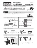
DRC200
Brand: Makita Pages: 2
DCL140
Brand: Makita Pages: 9


