


PRODUCT
P 1/ 9
Model No.
Description
C
ONCEPT AND MAIN APPLICATIONS
S
pecification
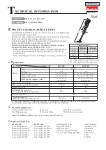
Standard equipment
Optional accessories
DCL140, DCL180
Cordless Cleaner
Models DCL140 and DCL180 are handy cordless cleaners of cloth filtration type
powered by Makita Li-ion battery;
DCL140 by battery of BL1415 (1.3Ah), BL1415N (1.5Ah), BL1415NA (1.5Ah),
BL1430 (3.0Ah), BL1430A (3.0Ah) or BL1440 (4.0Ah)
DCL180 by battery of BL1815 (1.3Ah), BL1815N (1.5Ah), BL1820 (2.0Ah),
BL1830 (3.0Ah), BL1840 (4.0Ah) or BL1850 (5.0Ah).
With the main benefits described below, optimum for cleaning operations
of contractors already having the Makita 14.4V or 18V:
・
Strong suction power and Large dust capacity for heavy-duty applications
・
Low noise design ideal for quiet cleaning operation in job sites among
residential areas
・
Rubberized soft grip for reduced hand fatigue even in long continuous use
Note:
The standard equipment may vary by country or model variation.
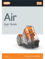
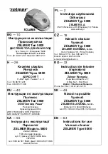
Nozzle assembly (T-nozzle)
Pipe (Extension pipe)
Sash nozzle
Sash nozzle holder
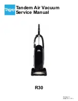
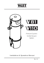
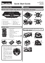
Dimensions: mm (")
Width (W)
Height (H)
Length (L2)
Length (L1)
981 (38-5/8) 999 (39-1/4)
458 (18)
476 (18-3/4)
114 (4-1/2)
152 (6)
DCL140
DCL180
*1
with Battery BL1430
*2
with Battery BL1830
*3
with Battery, without T-nozzle, Extension pipe and Sash nozzle
*4
with Battery BL1415/BL1415N
*5
with Battery BL1815/BL1815N/BL1820
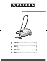
Nozzle assembly
(for rug/ carpet)
Shelf brush
Flexible hose
Round brush
Filter
Pre-filter
Max. sealed suction: kPa (mmH
2
O)
Max. air flow: m
3
/minute
Battery
Dust capacity: mL
Cell
Voltage: V
Capacity: Ah
Continuous use (approx.)
on a single full battery charge: minute
650
Suction power: W
Weight according to
EPTA-Procedure 01/2003
*
3
: kg (lbs)
Specification
Model
14.4
18
1.2
3.6 (360)
3.2 (320)
Li-ion
30
25
20
*
2
20
*
1
1.2 (2.6)
*
4
1.2 (2.7)
*
5
DCL140
DCL180
Charging time (approx.): min.
T
OFFICIAL USE
for ASC & Sales Shop
ECHNICAL INFORMATION
Energy capacity: Wh
1.3, 1.5, 3.0, 4.0
15, 15, 22, 36
with DC18RC
1.3, 1.5, 2.0, 3.0, 4.0, 5.0
19, 22, 44, 58
24, 27, 36, 54, 72, 90
15, 15, 24, 22, 36, 45
with DC18RC
For DCL140
Li-ion battery BL1415
Li-ion battery BL1415N
Li-ion battery BL1415NA
Li-ion battery BL1430
Li-ion battery BL1430A
Li-ion battery BL1440
For DCL180
Li-ion battery BL1815
Li-ion battery BL1815N
Li-ion battery BL1820
Li-ion battery BL1830
Li-ion battery BL1840
Li-ion battery BL1850
Fast charger DC18RC
Charger DC18SD
Charger DC24SC
Automotive charger DC18SE
Four port multi charger DC18SF
L2
L1
H
W
1.3
L1: without T-nozzle and Extension pipe
L2: with T-nozzle and Extension pipe
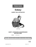
Filter (factory-mounted)
Pre-filter (factory-mounted)