


A. Serial Port Setup
- Function
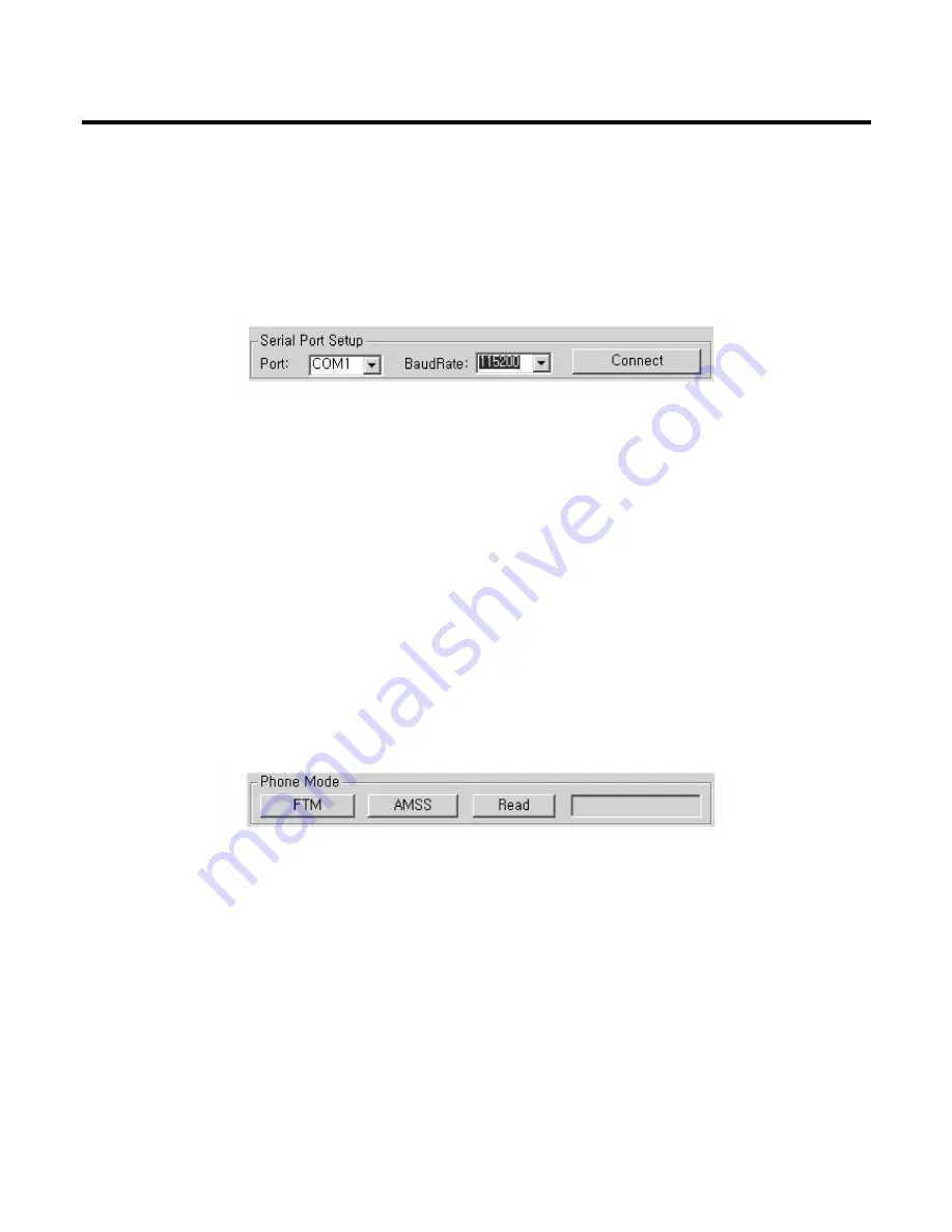
As shown in Figure 7-5, Serial Port Setup section supports setting the connection between PC and U8210.
- Procedure Proposal
1. First you have to setup your hardware: connect interface cable to one of the serial communication ports
(so COM1, COM2, COM3, or COM4) of your PC.
2. Setup the port number of PC.
3. Setup the baud-rate of 115200 bps (recommended value).
4. Click the ‘Connect’ button.
B. Phone Mode
- Function
As shown in Figure 7-6, Phone Mode Setup section supports the switching Advanced Mode Subscriber
Software (AMSS) mode and Factory Test Mode (FTM) mode. FTM is a mode of operation that allows a user
to perform diagnostic or design verification functionality by exposing functions not discretely available to the
user in AMSS mode. FTM does not provide the ability to make phone calls and is not driven by the
Advanced Mode Subscriber Software Call Processing State Machine.
- Procedure Proposal
1. Make sure the phone’s connection to PC.
2. To run calibration process, you should switch the phone mode of FTM mode. To switch FTM mode, click
the ‘FTM’ button. When the switching is done, the massage, “Set Phone FTM Status = SUCCESS!” on
debug screen blow and “FTM MODE” on status box near ‘Read’ button is displayed. If the mode switching
is fail, the message, “Set Phone FTM Status = FAIL!” is displayed on debug screen.
3. To make phone calls, you should switch the phone mode of AMSS mode. To switch AMSS mode, click
the ‘AMSS’ button. When the switching is done, the massage, “Set Phone AMSS Status = SUCCESS!”
on debug screen blow and “AMSS MODE” on status box near ‘Read’ button is displayed. If the mode
switching is fail, the message, “Set Phone AMSS Status = FAIL!” is displayed on debug screen.
4. To know phone’s mode, click the ‘Read’ button. The status box displays phone’s mode. When
disconnected phone and PC, the status box displays “UNKOWN MODE”.
7. CALIBRATION
- 186 -
Figure 7-5. Serial Port Setup
Figure 7-6. Phone Mode Setup
Summary of Contents for U8210
Page 22: ...3 TECHNICAL BRIEF 23 Figure 3 2 1 1 RTR6250 IC Functional Block Diagram ...
Page 37: ...3 TECHNICAL BRIEF 38 Figure 3 5 12 1 Bluetooth system architecture ...
Page 110: ...4 TROUBLE SHOOTING 111 USB_D USB_D USB_VBUS X100 48M 48MHz ...
Page 115: ...4 TROUBLE SHOOTING 116 LCD Control data flow ...
Page 117: ...4 TROUBLE SHOOTING 118 LCD Control data flow ...
Page 122: ...4 TROUBLE SHOOTING 123 TR400 ...
Page 124: ...4 TROUBLE SHOOTING 125 FLASH_ON from Main Bíd PM6650 CN1 Flash LED ...
Page 127: ...4 TROUBLE SHOOTING 128 FB503 CN500 FB502 CN2 CN1 ...
Page 129: ...4 TROUBLE SHOOTING 130 C627 Head_set Output Pin 4 5 C626 CN304 R624 ...
Page 131: ...4 TROUBLE SHOOTING 132 R649 CN300 CN2 CN1 U605 C633 R648 C634 R622 R623 ...
Page 133: ...4 TROUBLE SHOOTING 134 R649 CN300 CN2 CN1 U605 C633 R648 C634 R622 R623 ...
Page 135: ...4 TROUBLE SHOOTING 136 C627 Head_set Output Pin 4 5 C626 CN304 R624 ...
Page 137: ...4 TROUBLE SHOOTING 138 R649 CN300 CN2 CN1 U605 C633 R648 C634 R622 R623 ...
Page 139: ...4 TROUBLE SHOOTING 140 C627 Head_set Output Pin 4 5 C626 CN304 R624 ...
Page 141: ...4 TROUBLE SHOOTING 142 MIC Contact C404 C401 ...
Page 143: ...4 TROUBLE SHOOTING 144 C115 Head_Phone Input Pin 2 3 C102 CN304 R624 ...
Page 146: ...4 TROUBLE SHOOTING 147 Receptacle 4 6V 4 6V ...
Page 151: ...5 BLOCK DIAGRAM 152 Top Side ...
Page 152: ...5 BLOCK DIAGRAM 153 Bottom Side ...
Page 154: ...6 DOWNLOAD 155 It is ready for downloading ...
Page 160: ...6 DOWNLOAD 161 6 Click on Download to download ...
Page 165: ...6 DOWNLOAD 166 Downloading the Module image Finally Download has been complete ...
Page 168: ...6 DOWNLOAD 169 When you meet the NV Restore error Connect to the phone ...
Page 170: ...6 DOWNLOAD 171 Select the proper file and click on Restore Reading the NV file and restore NV ...
Page 200: ... 201 9 PCB LAYOUT ...
Page 201: ... 202 9 PCB LAYOUT ...
Page 202: ... 203 9 PCB LAYOUT U8210 KEYPAD SPEY0032001 1 1 TOP ...
Page 203: ... 204 9 PCB LAYOUT ...
Page 204: ... 205 9 PCB LAYOUT ...
Page 206: ... 207 ...
Page 207: ... 208 ...