
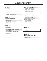
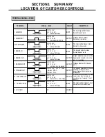
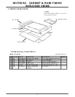

1-5
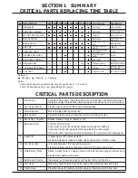
No. DESCRIPTION
1500 3000 5000 6000 7500 9000 10000 12000 Test freatures
Specification
1
DRUM ASSY
RF out level
-4dB and below
2
ARM ASSY CLEANER
Wear status
3
MOTOR CAPSTAN (D-35)
W/F(WTD)
0.4% and below
4
BELT CAPSTAN
Belt tension
5
BASE ASSY A/C
-6dB and below
6
HEAD F/E
45dB min
7
ARM ASSY IDLER
4~12 g
8
HOLDER ASSY PINCH
60~90
9
BAND ASSY TENSION
Back Torque
40~70 g
10
HOUSING ASSY
CST loading status
11
CAPSTAN SOFT BRAKE
Felt wear
12
CLUTCHAY
Torque(Play, Rev)
there shouldn’t be any space
betwween CST and compartment
whether there is
touch noise
40~140gcm, 100~210gcm
1. Drum
Ass’y
Consists of video head, rotary trans and motor. records video and audio information on
the tape, and play the tape back.
(Audio information is recorded only on the Hi-Fi models)
2.
Arm Ass’y Cleaner
Cleans video head and rotation head automatically.
4.
Motor Capstan
Moves the tape with regular speed.
5.
Belt Capstan
Transfers rotative energy of capstan motor to the driving system.
6.
Brake Ass’y Capstan
Brakes rotative energy of capstan motor.
7.
Base Ass’y A/C
Consists of three head.
Audio erase head in the left upper erases audio signal in dubbing.
Audio head in the right upper records and playes the audio signal.
CTL head in the right lower records and detects CTL pulse to control tape speed.
8.
Head F/E
Is abbreviation of Full Erased Head.
erases the signal recorded on a tape clearly and absorb vibration of tape.
12. Arm Ass’y Idler
Is located between T/UP reel and supply reel.
Transfers ratative energy of capstan motor to T/UP reel or supply reel.
13. Holder Ass’y Pinch
Sticks a video tape to capstan motor and has the tape played without being
slipped from capstan motor axle.
14. Band Ass’y Tension
Has supply reel loosened properly with giving it some tensile force.
15. Arm Ass’y
Makes the cassette tape inserted be loaded and ejected precisly and safely.
16. Clutch Ass’y
Plays the tape with trasfering rotative energy of capstan motor to idler reel.
SECTION1 SUMMARY
CRITICAL PARTS REPLACING TIME TABLE
Audio and CTL out
level
Whether extraneous
matters come out
Variation amount :
within 40%
The rate of erasing
(1KHz)
The capacity of ldler
for moving
Surrace solidity of
Roller
Reference :
Changing
Cleaning
Checking
Notes :
• Check the running path adjustment when you change the itens 1, 3, 5, 6 and 10.
• Check the back tension when you change Band Assy Tension.
CRITICAL PARTS DESCRIPTION
Summary of Contents for TL-AT130M
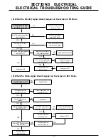
Page 23: ...3 14 3 13 SECTION3 ELECTRICAL BLOCK CIRCUIT DIAGRAMS 1 OVERALL WIRING DIAGRAM ...
Page 24: ...3 16 3 15 SECTION3 ELECTRICAL BLOCK CIRCUIT DIAGRAMS 2 POWER BLOCK DIAGRAM ...
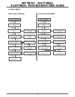
Page 25: ...3 18 3 17 SECTION3 ELECTRICAL BLOCK CIRCUIT DIAGRAMS 3 POWER CLRCUIT DIAGRAM ...
Page 26: ...3 19 SECTION3 ELECTRICAL BLOCK CIRCUIT DIAGRAMS 4 AUDIO BLOCK DIAGRAM ...
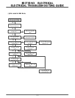
Page 27: ...3 20 SECTION3 ELECTRICAL BLOCK CIRCUIT DIAGRAMS 5 Y C BLOCK DIAGRAM ...
Page 28: ...3 22 3 21 SECTION3 ELECTRICAL BLOCK CIRCUIT DIAGRAMS 6 A V CIRCUIT DIAGRAM ...
Page 29: ...3 23 SECTION3 ELECTRICAL BLOCK CIRCUIT DIAGRAMS ...
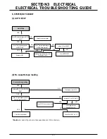
Page 30: ...3 25 3 24 SECTION3 ELECTRICAL BLOCK CIRCUIT DIAGRAMS 7 SYSTEM BLOCK DIAGRAM ...
Page 31: ...3 26 SECTION3 ELECTRICAL BLOCK CIRCUIT DIAGRAMS ...
Page 32: ...3 28 3 27 SECTION3 ELECTRICAL BLOCK CIRCUIT DIAGRAMS 8 SYSTEM CLRCUIT DIAGRAM ...
Page 33: ...3 30 3 29 SECTION3 ELECTRICAL BLOCK CIRCUIT DIAGRAMS 9 JACK CLRCUIT DIAGRAM ...
Page 34: ...3 32 3 31 SECTION3 ELECTRICAL BLOCK CIRCUIT DIAGRAMS 10 KEY BOARD CLRCUIT DIAGRAM ...
Page 35: ...3 34 3 33 SECTION3 ELECTRICAL PRINTED CIRCUIT DIAGRAMS 1 MAIN P C BOARD ...