MAINTENANCE/INSPECTION PROCEDURE
4-20
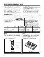
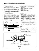
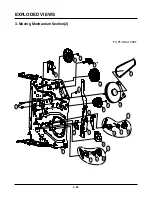
2. Required Maintenance
The recording density of a VCR(VCP) is much higher than
that of an audio tape recorder. VCR(VCP) components must
be very precise, at tolerances of 1/1000mm, to ensure com-
patibility with the other VCRs. If any of these components are
worn or dirty, the symptoms will be the same as if the part is
defective. To ensure a good picture, periodic inspection and
maintenance, including replacement of worn out parts and
lubrication, is necessary.
3. Scheduled Maintenance
Schedules for maintenance and inspection are not fixed
because they vary greatly according to the way in which the
customer uses the VCR(VCP), and the environment in which
the VCR(VCP) is used.
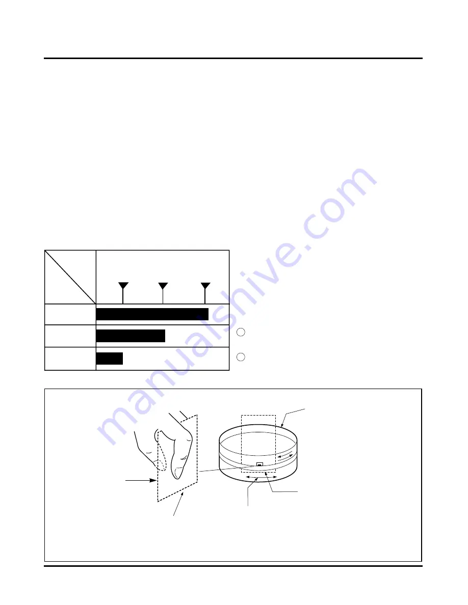
But, in general home use, a good picture will be maintained
if inspection and maintenance is made every 1,000 hours.
The table below shows the relation between time used and
inspection period.
Table 1
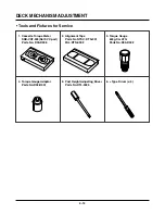
4. Supplies Required for Inspection and
Maintence
(1) Grease : Kanto G-311G (Blue) or equivalent
(2) Isopropyl Alcohol or equivalent
(3) Cleaning Patches
(4) Grease : Kanto G-381(Yellow)
5. Maintenance Procedure
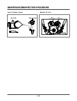
5-1) Cleaning
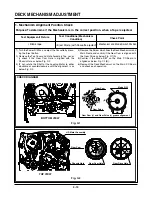
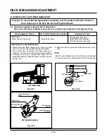
(1) Cleaning video head
First use a cleaning tape. If the dirt on the head is too
stubborn to remove by tape, use the cleaning patch. Coat
the cleaning patch with Isopropyl Alcohol. Touch the
cleaning patch to the head tip and gently turn the
head(rotating cylinder) right and left.
(Do not move the cleaning patch vertically. Make sure
that only the buckskin on the cleaning patch comes into
contact with the head. Otherwise, the head may be dam-
aged.)
Thoroughly dry the head. Then run the test tape. If lso-
propyl Alcohol remains on the video head, the tape may
be damaged when it comes into contact with the head
surface.
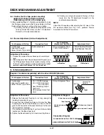
(2) Clean the tape transport system and drive system, etc, by
wiping with a cleaning patch wetted with Isopropyl
Alcohol.
NOTES:
1
It is the tape transport system which comes into contact
with the running tape. The drive system consists of those
parts which moves the tape.
2
Make sure that during cleaning you do not touch the tape
transport system with excessive force that would cause
deformation or damage to the system.
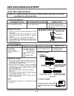
About 1
year
One hour
Two hours
Three hours
When
inspection is
necessary
Average
hours used
per day
About 18
months
About 3
years
Fig. C-9-4
Drum
(Rotating Cylinder)
Head Tip
Coat With Isopropyl Alcohol
Touch this section of cleaning
patch to the head tip and gently
turn the Drum (Rotating Cylinder)
Cleaning Patch
Summary of Contents for TL-AT130M
Page 23: ...3 14 3 13 SECTION3 ELECTRICAL BLOCK CIRCUIT DIAGRAMS 1 OVERALL WIRING DIAGRAM ...
Page 24: ...3 16 3 15 SECTION3 ELECTRICAL BLOCK CIRCUIT DIAGRAMS 2 POWER BLOCK DIAGRAM ...
Page 25: ...3 18 3 17 SECTION3 ELECTRICAL BLOCK CIRCUIT DIAGRAMS 3 POWER CLRCUIT DIAGRAM ...
Page 26: ...3 19 SECTION3 ELECTRICAL BLOCK CIRCUIT DIAGRAMS 4 AUDIO BLOCK DIAGRAM ...
Page 27: ...3 20 SECTION3 ELECTRICAL BLOCK CIRCUIT DIAGRAMS 5 Y C BLOCK DIAGRAM ...
Page 28: ...3 22 3 21 SECTION3 ELECTRICAL BLOCK CIRCUIT DIAGRAMS 6 A V CIRCUIT DIAGRAM ...
Page 29: ...3 23 SECTION3 ELECTRICAL BLOCK CIRCUIT DIAGRAMS ...
Page 30: ...3 25 3 24 SECTION3 ELECTRICAL BLOCK CIRCUIT DIAGRAMS 7 SYSTEM BLOCK DIAGRAM ...
Page 31: ...3 26 SECTION3 ELECTRICAL BLOCK CIRCUIT DIAGRAMS ...
Page 32: ...3 28 3 27 SECTION3 ELECTRICAL BLOCK CIRCUIT DIAGRAMS 8 SYSTEM CLRCUIT DIAGRAM ...
Page 33: ...3 30 3 29 SECTION3 ELECTRICAL BLOCK CIRCUIT DIAGRAMS 9 JACK CLRCUIT DIAGRAM ...
Page 34: ...3 32 3 31 SECTION3 ELECTRICAL BLOCK CIRCUIT DIAGRAMS 10 KEY BOARD CLRCUIT DIAGRAM ...
Page 35: ...3 34 3 33 SECTION3 ELECTRICAL PRINTED CIRCUIT DIAGRAMS 1 MAIN P C BOARD ...