LG STB1000, Installation & Setup Manual
The LG STB1000 Installation & Setup Manual is a comprehensive guide that ensures a seamless setup experience for your device. This essential manual offers step-by-step instructions, troubleshooting tips, and insightful information to maximize your product's potential. Download this manual for free from manualshive.com and unlock the full potential of your LG STB1000.
Share
Download


Reviews:
No comments
Related manuals for STB1000
M5
Brand: N-Com Pages: 32

SB-110
Brand: Oakcastle Pages: 28
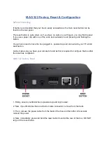
322
Brand: MAG Pages: 10
RNG200N
Brand: Pace Pages: 2
FV200
Brand: Labgear Pages: 16

GX-SM530CF
Brand: Samsung Pages: 3
SIR-T351
Brand: Samsung Pages: 52
Datacom TDT-HD140
Brand: Datacom Pages: 31
KSTB2020
Brand: Kaon Pages: 32
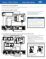
TDC775D
Brand: Pace Pages: 2

TDC777D
Brand: Pace Pages: 29

YouView
Brand: TalkTalk Pages: 24
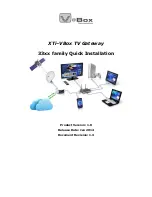
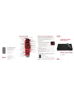
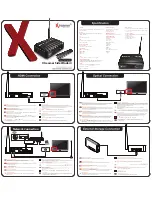
XTi-
Brand: VBOX Pages: 10
HDT-610R Wi-Fi
Brand: EchoStar Pages: 2

EtherneTV MPEG-1
Brand: VBrick Systems Pages: 58
SideWinder4
Brand: Xtreamer Pages: 2
H7
Brand: ZGEMMA Pages: 32
ZAT-600B
Brand: Zinwell Pages: 4


