background image

- 5 -

DESCRIPTION OF CONTROLS

Function Status Indicators

Lamp indicator, operation indicator, and temperature indicator located below the front panel

controls, reveal the operating status of the LCD projection TV.

Operation Indicator

Lamp Indicator

Temperature Indicator

Off 

TV is not connected to power outlet.

Red 

Power Cord is connected, TV is in standby mode.

Green 

On

Orange (flashing)

Preparing operation in standby mode.

Orange 

Projection lamp is reaching the end of its life and needs to 

be replaced with a new lamp.

Red (flashing)

There is a problem with the lamp or around it. Contact an 

authorized service center.

Green (flashing)

The lamp cover is not closed.

Orange

The projection TV is overheating.

Red

The projection TV shut down due to overheating.

Red (flashing)

The projection TV shut down, check the cooling fan. 

Operation Indicator

Lamp Indicator

Temperature Indicator

Summary of Contents for RU-48SZ40

Page 1: ...V SERVICE MANUAL CAUTION BEFORE SERVICING THE CHASSIS READ THE SAFETY PRECAUTIONS IN THIS MANUAL CHASSIS NB 03JA MODEL RU 48SZ40 CANADA http biz lgservice com USA http www lgservice com http lgservice com techsup html ...

Page 2: ...ECTROSTATICALLY SENSITIVE ES DEVICES 4 DESCRIPTION OF CONTROLS 5 SPECIFICATION 12 ADJUSTMENT INSTRUCTIONS 13 REPLACING THE LAMP 19 BLOCK DIAGRAM 20 EXPLODED VIEW 24 EXPLODED VIEW PARTS LIST 25 REPLACEMENT PARTS LIST 26 SCHEMATIC DIAGRAM PRITED CIRCUIT BOARD 2 ...

Page 3: ...ngs Place the AC switch in the on positioin connect one lead of ohm meter to the AC plug prongs tied together and touch other ohm meter lead in turn to each exposed metallic parts such as antenna terminals phone jacks etc If the exposed metallic part has a return path to the chassis the measured resistance should be between 1MΩ and 5 2MΩ When the exposed metal has no return path to the chassis the...

Page 4: ...ductive parts INSULATION CHECKING PROCEDURE Disconnect the attachment plug from the AC outlet and turn the power on Connect the insulation resistance meter 500 V to the blades of the attach ment plug The insulation resistance between each blade of the attachment plug and accessible conductive parts Note 1 should be more than 1 Mohm Note Accessible conductive parts include metal panels input termin...

Page 5: ...d TV is in standby mode Green On Orange flashing Preparing operation in standby mode Orange Projection lamp is reaching the end of its life and needs to be replaced with a new lamp Red flashing There is a problem with the lamp or around it Contact an authorized service center Green flashing The lamp cover is not closed Orange The projection TV is overheating Red The projection TV shut down due to ...

Page 6: ... Channel Display Displays current channel number Channel Label If a channel label has been set then it will appear here PIP Display This display appears when PIP is active Volume Volume level is displayed while adjusting the sound Mute Appears when sound is muted Time Appears if the Enter button is pressed on remote control ABC ...

Page 7: ...indicator Temperature indicator POWER MENU ENTER Same as ENTER button on your remote control VOLUME UP DOWN CHANNEL UP DOWN 1 2 3 4 5 6 7 8 See menu pages for instructions on using the on screen menus The POWER CHANNEL TV VIDEO and VOLUME buttons work just as they do on your remote control ...

Page 8: ...O Selects Analog Video1 Video2 Front video Component1 2 RGB and DVI input sources LIGHT Illuminates the remote control keys FRONT Selects the front video signal if a device such as a camcorder or game player is connected to the front video input jack COMP DVI Selects Component1 2 RGB and DVI input sources PIP Toggles between PIP POP Picture out of Picture and Twin picture mode FREEZE Captures and ...

Page 9: ...hannel AUDIO Selects the sound appropriate for the program s character RECORD PAUSE REW FFWD PLAY STOP Control the functions on your VCR VOLUME UP DOWN Increases decreases the sound level RATIO Changes the screen format or aspect ratio SKIP Playing CDs Selects songs Playing DVDs Selects movie chapters ENTER When in the menu system and other on screen displays selects highlighted options FLASHBK Tu...

Page 10: ... sub woofer to your surround sound sys tem RF Connector Antenna Used to connect analog cable or antenna signals to the television either directly or through your cable box Video 1 or 2 Connects the video sig nals from various types of equipment Y Pb Pr DVD Component Video and HD Component Video Some top of the line DVD players use what is called component video for extremely accurate picture repro...

Page 11: ...enu Left Right Audio Used for stereo sound from various types of equipment Video Connects the video signals from any piece of equipment S Video A connection available on some very high end equip ment that provides better picture quality than video input If you select either Front Video or Front S Video the Front audio inputs are automatically selected as well If you re connecting a video game devi...

Page 12: ... Consumption W 270W Antenna 75 ohm External Terminal for VHF UHF Audio Output W 15W x 2 Supplied Accessories Remote control 2 size AA batteries External Input Output Ports Audio Video inputs 3 sets Audio Video output 1 set S Video inputs 2 Component inputs 2 sets RGB input 1 DVI input 1 RGB DVI audio input 1 set Variable audio output 1 set Audio center mode input 1 Calibration port 1 External Spea...

Page 13: ...selected by IN START key RGB alignment is selected in this case 2 Step123 Step selection when changing data ex Step123 1 Change one by one when changing data with Volume key Step123 10 Change ten by ten when changing data with Volume key You can select 1 by press number key 1 10 by press 12 100 by press 123 And you can change data by 1 10 100 3 10 H_position 315 315 315 Actual adjusting menu 4 Mic...

Page 14: ...embling Adjustment 5 1 Screen Tilt Keystone Adjustment 1 Required Test Equipments 1 Six angles wrench and spanner for knob adjustment or fix ation 2 XGA output PC 3 Remote Control 2 Preparation for Adjustment 1 Do not assemble the front pannel equipment so that you can adjust the adjustment knob Fig 3 2 Turn the TV ON and select input mode to RGB_PC 3 Connect XGA output terminal to PC input of TV ...

Page 15: ...vel 2 A equipment composition Adjust at the same condition of equipment composition diagram 3 Preparation for Adjustment Compose the equipment follow Fig 2 and place the set on the fixation stand 1 Select the VDP Test Pattern signal to R1 G1 B1 2 Press the IN START key to select 4 62352 and then select 5 RVREF 8 GVREF 12 BVREF in adjust mode 3 Adjust the luminance of CA100 below 0 75Cd The adjust ...

Page 16: ...and correct register value if need Resister Explanation about uniformity adjustment 1 RamCtrl s w saving uniformity write order Do not adjust 2 CSHP Horizontal start point designation adjustable 3 CSVP Vertical start point designation adjustable 4 CEHP Horizontal END point designation adjustable 5 CEVP Vertical END point designation adjustable 6 Mode uniformity mode select adjustable if need 0 221...

Page 17: ... Level of R Max level when 3coefficient 32 RLMAX Setting up the MAX Level of R 33 GLMIN Setting up the MINIUM Level of G Set under 200 34 GLMID2 Setting up the MIDDLE 2nd Level of G Middle level when 3coefficient 35 GLMID1 Setting up the MIDDLE 1st Level of G Max level when 3coefficient 36 GLMAX Setting up the MAX Level of G 37 BLMIN Setting up the MINIUM Level of B Set under 200 38 BLMID2 Setting...

Page 18: ...ttern and if there is difference adjust like this The field and the letters are distinguished 4 Adjusting Main screen 1 Press the IN Start key on R C for adjustment to select 1 VPX3226 main 2 Adjust to 16 Contrast of adjustment item with key initial value 32 5 Adjusting Sub screen 1 Press the IN Start key on R C for adjustment to select 2 VPX3226 sub 2 Adjust to 16 Contrast of adjustment item with...

Page 19: ... remove the lamp case 6 Insert the new lamp gently into the correct position Make sure it is inserted cor rectly 7 Tighten the screw you removed in step 3 8 Replace the lamp cover and tighten the cover screws Make sure the almp cover is securely fastend If lamp cover is open the lamp indicator flashes green and the projector is not turn on Resetting the lamp time After pressing the key on the remo...

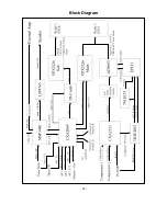
Page 20: ...Block Diagram 20 ...

Page 21: ... 21 ...

Page 22: ... 22 ...

Page 23: ... 23 ...

Page 24: ... 300 304 590 174 630 305 301 302 520 503 550 501 530 540 600 201 200 202 211 213 214 560 219 640 217 570 212 216 218 620 600 403 580 402 420 210 220 215 Disassemble 302 and remove 2 screw of 300 bottom center to separate 300 from 400 ...

Page 25: ...00015A SCREEN ASSEMBLY DNP NON RN 48SZ40H 1094 617 305 3790V00702A FILTER MECH WINDOW 48W LCD PJTV ACRYL DIABELL XCANVAS 310 5020V00751A BUTTON CONTROL RN 48SZ40 ABS HF 380 7KEY 400 3809V00324H BACK COVER ASSEMBLY RU 48SZ40 NON UPPER 402 3550V00278F COVER LAMP RU 48SZ40 ABS AF 303S V000014 3858VC0038D 403 3110V00257A CASE NON RN48SZ40H PC ABS LAMP DUCT 410 3809V00325C BACK COVER ASSEMBLY RZ 48SZ40...

Page 26: ...OCA NO PART NO DESCRIPTION IC01 IC02 IC1 IC100 IC1001 IC1002 IC1004 IC101 IC101 IC102 IC1100 IC1101 IC1102 IC1103 IC1104 IC1105 IC1106 IC1107 IC1200 IC1200 IC1202 IC1202 IC1203 IC1300 IC1301 IC1302 IC1303 IC1304 IC1305 IC1400 IC1401 IC1402 IC1403 IC1404 IC1405 IC1500 IC1501 IC1502 IC1503 IC1504 IC1505 IC1602 IC2 IC200 IC208 IC301 IC303 0IMI623200B 0IMI623200B 0IZZVC0051K 0IMCRS5003A 0IPRPFA006A 0I...

Page 27: ... ALY KEC CHIP 2SC3875S ALY KEC CHIP 2SC3875S ALY KEC CHIP 2SC3875S ALY KEC CHIP 2SC3875S ALY KEC CHIP 2SC3875S ALY KEC LOCA NO PART NO DESCRIPTION Q500 Q501 Q502 Q504 Q601 Q601 Q602 Q602 Q603 Q605 Q605 Q810 Q841 Q842 Q851 D01 D02 D03 D1 D100 D101 D2 D3 D300 D404 D430 D431 D432 D433 D435 D436 D437 D438 D439 D5 D601 D603 D605 D606 D607 D801 D801 D802 D803 D804 D805 D806 D810 D820 D821 0TR150400BA 0T...

Page 28: ...MV 16V 20 47UF MV 50V 20 47UF MVG 16V M 10UF MV 16V 20 22UF MV 16V 20 LOCA NO PART NO DESCRIPTION C110 C1100 C1101 C1102 C1103 C1104 C1105 C1106 C1107 C1108 C111 C1110 C1111 C1112 C1114 C1116 C1118 C112 C112 C1122 C1125 C1133 C1134 C1138 C1139 C1143 C117 C1200 C1201 C1202 C1202 C1204 C1205 C1206 C1207 C1208 C1209 C1216 C1217 C1218 C1226 C1234 C1237 C124 C1250 C1251 C126 C128 C129 C1301 C1305 C1308...

Page 29: ...01UF 1608 50V 10 0 01UF 1608 50V 10 47UF MV 25V 20 LOCA NO PART NO DESCRIPTION C1525 C1529 C1535 C1536 C1541 C16 C1620 C1621 C2 C20 C200 C202 C204 C205 C205 C206 C209 C212 C216 C218 C222 C223 C227 C228 C231 C245 C246 C247 C247 C248 C250 C252 C260 C261 C262 C29 C3 C312 C314 C406 C406 C407 C408 C409 C410 C411 C412 C427 C428 C434 C435 C437 0CE476VH6DC 0CE476VH6DC 0CE476VH6DC 0CE476VH6DC 0CE476VH6DC 0...

Page 30: ...RT NO DESCRIPTION C669 C800 C801 C801 C801B C802 C804 C804 C805 C806 C806 C807 C807 C808 C809 C814 C814 C818 C818 C820 C821 C822 C823 C824 C825 C829 C831 C832 C832 C833 C835 C836 C837 C841 C843 C845 C853 C855 C856 C858 C859 C862 C865 C873 C876 C881 C883 C884 C886 JA1201 0CE105VK6DC 0CE106SF6DC 0CK105DF64A 0CQZVBK002B 0CE106BK618 0CQZVBK002A 0CE106SF6DC 0CF1050W470 0CK10202510 0CE226SF6DC 0CK102025...

Page 31: ...M 1 16 W 1608 5 22 OHM 1 16 W 1608 5 22 OHM 1 16 W 1608 5 22 OHM 1 16 W 1608 5 LOCA NO PART NO DESCRIPTION AR1213 AR1214 AR1215 AR1216 AR1217 AR301 AR302 AR303 AR304 AR305 AR306 R1 R1253 R2 R3 R4 R5 R56 R57 R58 R632 R634 R666 R667 R668 R673 R801B R802B R803 R803 R803B R805 R805B R806 R806 R807 R807 R808 R809 R810 R811 R812 R813 R814 R815 R816 R817 R818 R819 R820 R821 R822 0RRZVTA001D 0RRZVTA001D 0...

Page 32: ... T1304 T1401 T1402 T1403 T1404 T1501 T1502 T1503 T1504 T200 T3 T400 T401 T402 T402 T403 0LCCE00018A 0LCCE00018A 0LCCE00018A 0LCCE00018A 0LCCE00018A 0LCCE00018A 0LCCE00018A 0LCCE00018A 0LCCE00018A 0LCCE00018A 125 123A 125 022K 125 123A 125 022K 125 022K 125 022K 6200C000009 6210TCE001G 6210TCE001G 6210TCE001G 6210TCE001G 150 F06T 150 F06T 150 F06T 150 F06T 6200C000009 6200C000009 6200C000010 6200C0...

Page 33: ...0MA FILTER EMC BMS400 25V 200MA FILTER EMC BMS400 25V 200MA FILTER EMC BMS400 25V 200MA FILTER EMC BMS400 25V 200MA FILTER EMC BMS400 25V 200MA FILTER EMC BMS400 25V 200MA FILTER EMC BMS400 25V 200MA FILTER EMC BMS400 25V 200MA FILTER EMC BMS400 25V 200MA FILTER EMC BMS400 25V 200MA FILTER EMC BMK800 50VOLT 1A FILTER EMC BMK800 50VOLT 1A FILTER EMC BMK800 50VOLT 1A FILTER EMC BMK800 50VOLT 1A RESO...

Page 34: ...d in Korea P NO 3828VD0148V CANADA LG Electronics Canada Inc 550 Matheson Boulevard East Mississauga Ontario L4Z 4G3 USA LG Customer Interactive Center P O Box 240007 201 James Record Road Huntsville AL 35824 ATTN CIC ...

Page 35: ......

Page 36: ......

Page 37: ......

Page 38: ......

Page 39: ......

Page 40: ...T BOARD MAIN TOP MAIN BOTTOM SMPS TUNER TOP COMPONENT TOP COMPONENT BOTTOM TUNER BOTTOM DIGITAL TOP DIGITAL BOTTOM LINE FILTER DRIVER TOP DRIVER BOTTOM CONTROL TOP CONTROL BOTTOM BALLAST INT PRE AMP SIDE A V CASE S W ...

Reviews: