


3. ACP operation by using the LG ACCS
ACP
3-14
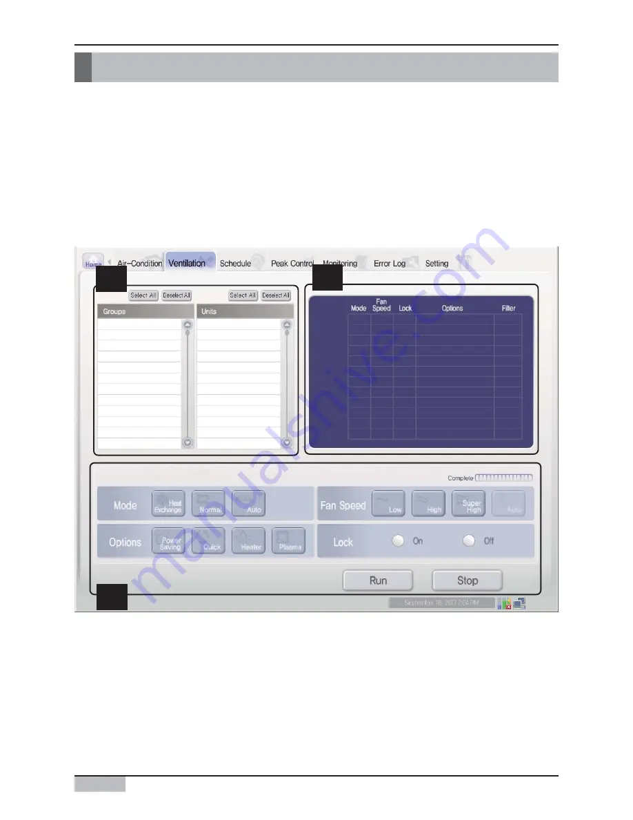
Controlling the ventilator
You can use the LG ACCS to control the functions such as selecting the ventilating group and the
ventilator, the operation mode, the air flow, the additional function and the lock.
The ventilation control function has the following advantages:
• It can centrally control all the installed ventilators by the computer screen.
• It can easily operate and monitor.
• It can perform the integrated control by the group setting.
Click 'Ventilating' menu at the top of the LG ACCS for controlling the ventilator. Click 'Ventilating'
menu to display the following screen for controlling the ventilator.
1
2
3
Summary of Contents for PQCPA11A0E
Page 163: ......


