4-4
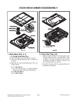
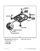
3. Base Assembly Sled (Fig. 4-3)
1) Release 4 Screw(S2).
2) Disconnect the FFC Connector(C1)
3-1.
Gear Feed
3-2. Gear Middle
3-3.
Gear Rack
4. Rubber Rear (Fig. 4-3)
BASE PU
RUBBER DAMPER
RUBBER DAMPER
RUBBER DAMPER
Distinguish upper and
lower sides
(Assemble with care)
Distinguish upper and
lower sides
(Assemble with care)
RUBBER DAMPER
Fig. 4-3
(S2)
(S2)
(S2)
(S2)
GEAR RACK
GENERAL PICK UP ASSEMBLY
SPINDLE MOTOR ASSEMBLY
Summary of Contents for OM7560
Page 13: ...1 12 ...
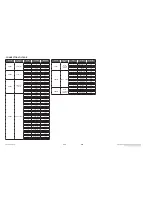
Page 19: ...2 8 ...
Page 53: ...3 34 2 SDRAM IC502 Fig 2 SDRAM 7 6 8 5 8 6 7 5 ...
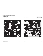
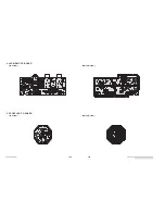
Page 66: ...3 77 3 78 2 MAIN P C BOARD TOP VIEW ...
Page 67: ...3 79 3 80 MAIN P C BOARD BOTTOM VIEW ...
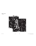
Page 68: ...3 81 3 82 3 TOP FRONT P C BOARD TOP VIEW ...

