

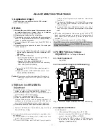


1. Application Object
These instructions are applied to all of the PDP monitor/
Tuner , RF-03FA chassis.
2. Notes
(1) Because this is not a hot chassis, it is not necessary to use
an isolation transformer. However, the use of isolation
transformer will help protect test instrument.
(2) Adjustment must be done in the correct order.
(3) The adjustment must be performed in the circumstance of
25±5°C of temperature and 65±10% of relative humidity if
there is no specific designation.
(4) The input voltage of the receiver must keep 220V, 60Hz in
adjusting.
(5) The receiver must be operated for about 15 minutes prior
to the adjustment.
¤
After receiving 100% white pattern, the receiver must be
operate prior to adjustment.(Or white condition in HEAT-
RUN mode)
¤Ł
Enter into HEAT-RUN mode
- Select the HEAT-RUN OFF by pressing ADJ Key on
Remote Control for adjustment.
- Press the VOL + Key in HEAT-RUN OFF.
(OSD display HEAT-RUN WHITE and screen display
100% FULL WHITE PATTERN)
[
Set is activated HEAT-RUN without signal generator in
this mode.
[
Single color pattern of HEAT-RUN mode uses to check
PANEL.(RED/BLUE/GREEN)
[Caution] If you turn on a still screen more than 20 minutes, a
afterimage may be occur in the black level part of the
screen.
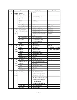
3. RGB Auto Cut-Off & MIN Bia
Adjustment
(1) Input Full Back (0 Gray) signal which generated from
Pattern Generator into CVBS and RGB1 Input part.
(2) Press POWER ON KEY on R/C for adjustment and select
AUTO-CUT(Cut-off Auto Adjustment)
(3) Press Vol. + key and operate TO SET
(4) Screen adjustment starts with Full Black screen.
Original Window screen will be presented about 3-5
seconds later. And if there is a mark of OK OSD, then the
Auto Cut-off and Min-Bias adjustment will be completed.
(5) Pass to the next MAX Bias Adjustment after Adjustment.
[
Replace PDP Module or Power Board, adjust certainly
Power PCB Assy Voltage.
O
You can check whether circuit adjustment is operated well or
not, as below.
(1) Display RGB1 to the Main picture, CVBS to the Sub
picture in the TWIN PICTURE.
(2) To check the MIN-Bias, input Full Black (0 gray) signal into
CVBS and RGB1 input part at the same time in the Pattern
Generator.
(3) To check the MAX-Bias, input Full White (255 gray) signal
into CVBS and RGB1 input part at the same time in the
Pattern Generator.
(4) Compare Black Level with White Level by eyes. And if
there is no Level difference, the adjustment is completed
well.
O
Data value, which adjusted in the board, is valid until the VSC
Board is dissued and must be protected. For the protection of
data, Micom does not permit any more adjustment after
completion.
O
In case of re-adjustment, operate First Value Setting.
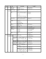
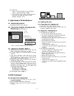
4. POWER PCB Assy Voltage
Adjustment
(Va, Vs, Voltage Adjustment)
4-1. Test Equipment
D.M.M 1EA
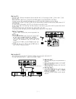
4-2. Connection Diagram for Measuring
4-3. Adjustment Method
(1) Va Adjustment
¤
After receiving 100% white pattern, HEAT RUN.
¤Ł
C terminal of D.M.M to Va pin of CN803 and
connect – terminal to GND pin of CN803.
¤Ø
After turning the VR351, voltage of D.M.M adjustment
as same as Va voltage which on label of panel
Right/Top. (Deviation : ±0.5V)
- 21 -
ADJUSTMENT INSTRUCTIONS
Each PCB Assy must be checked by the Check JIG Set before
whole assembly. (Be careful the POWER PCB Assy not to
damage to PDP Module)
Va ADJ
VR351
Vs ADJ
VR551
CN 804
CN 803
CN 802
CN 810
CN 809
CN 808
VS
Va
Va
GND
GND
VS
VS
5V
<Fig 1> Connection Diagram of MURATA Power Adj. for Measuring
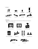
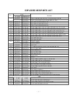
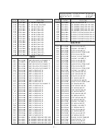
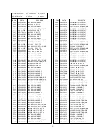
Summary of Contents for MT-42PZ44
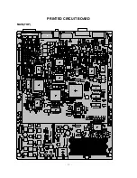
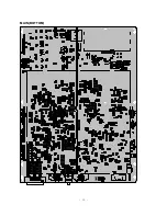
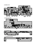
Page 25: ... 25 MAIN TOP PRINTED CIRCUIT BOARD ...
Page 26: ... 26 MAIN BOTTOM ...
Page 27: ... 27 AV BOARD TOP AV BOARD BOTTOM AV FIX BOARD TOP AV FIX BOARD BOTTOM ...
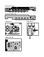
Page 28: ... 28 CONTROL BOARD TOP CONTROL BOARD BOTTOM POWER SWITCH SPEAKER TOP SPEAKER BOTTOM ...
Page 29: ...MEMO 29 ...
Page 43: ......
Page 44: ......
Page 45: ......
Page 46: ......
Page 47: ......
Page 48: ......
Page 49: ......
Page 50: ......
Page 51: ......
Page 52: ......
Page 53: ... ÆFor europe ...
Page 54: ... ÆFor asia ...
Page 55: ...SVC SHEET 3854V A0133A S1 SVC SHEET 3854V A0133A S2 SVC SHEET ...


