4. TROUBLE SHOOTING
- 43 -
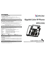
• Trouble Shooting Setup
- Connect Battery & TA to the handset
• Trouble Shooting Procedure
START
I/O Connector (CN202)
Is well ñ soldered ?
Voltage at pin 1 of U201
=4.8 V ?
Yes
Voltage at pin 5 of U201
Is LOW in case charging?
Yes
Yes
Battery is OK ?
Yes
Charging is operating properly
Resolder the CN202
(Pin 12,13)
No
The TA is out of order.
Change the TA
Change the TA.
No
The Battery may have
Problems. Change battery.
No
No
The IC is out of order
Change the IC
CHG _enable
V _ bat
Charging Current
Charging Enable
V _ chg
Summary of Contents for MG810c
Page 1: ...Date May 2006 Issue 1 0 Service Manual MG810c MG810d Service Manual Model MG810c MG810d ...
Page 3: ... 2 ...
Page 5: ......
Page 46: ...4 TROUBLE SHOOTING 45 WR CS ADSSSSS CS ADSSSSS WR ...
Page 52: ...4 TROUBLE SHOOTING 51 G 1 Speaker Receiver Trouble Shooting Common Path ...
Page 53: ...4 TROUBLE SHOOTING 52 G 2 Speaker Receiver Trouble Shooting Acoustic Path ...
Page 54: ...4 TROUBLE SHOOTING 53 G 3 Speaker Receiver Trouble Shooting MP3 AAC Path ...
Page 55: ...4 TROUBLE SHOOTING 54 G 4 Speaker Receiver Trouble Shooting FM Radio Path ...
Page 56: ...4 TROUBLE SHOOTING 55 G 5 Main Mic Path Trouble Shooting ...
Page 57: ...4 TROUBLE SHOOTING 56 G 6 Ear Mic Receiver Path Trouble Shooting ...
Page 58: ...4 TROUBLE SHOOTING 57 G 7 Ear Mic Mic Path Trouble Shooting ...
Page 59: ...4 TROUBLE SHOOTING 58 G 8 Vibrator Trouble Shooting ...
Page 60: ...4 TROUBLE SHOOTING 59 4 2 RF Part Troubleshooting A RF Receiving Path Trouble Shooting ...
Page 64: ...4 TROUBLE SHOOTING 63 E RF Receiving Path Trouble Shooting FEM 1 ...
Page 65: ...4 TROUBLE SHOOTING 64 F RF Receiving Path Trouble Shooting FEM 2 ...
Page 67: ...4 TROUBLE SHOOTING 66 H RF Transmitter Path Trouble Shooting ...
Page 73: ...4 TROUBLE SHOOTING 72 N RF Transmitter Path Trouble Shooting FEM 1 ...
Page 74: ...4 TROUBLE SHOOTING 73 O RF Transmitter Path Trouble Shooting FEM 2 ...
Page 84: ...6 Block Diagram 83 6 Block Diagram ...
Page 85: ... 84 ...
Page 96: ... 95 8 PCB LAYOUT ...
Page 97: ... 96 8 PCB LAYOUT ...
Page 98: ... 97 8 PCB LAYOUT ...
Page 99: ... 98 8 PCB LAYOUT ...
Page 100: ... 99 8 PCB LAYOUT ...
Page 101: ... 100 8 PCB LAYOUT ...
Page 111: ... 110 ...
Page 113: ... 112 ...
Page 133: ...Note ...
Page 134: ...Note ...