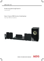
1-5
SPECIFICATIONS
• GENERAL
Power supply
Refer to the back panel of the unit.
Power consumption
Refer to the back panel of the unit.
Net Weight
3.00kg
External dimensions (WxHxD)
300 x 130 x 243mm
• CD/DVD
Laser
Semiconductor laser, wavelength 650nm
Signal system
PAL 625/50, NTSC 525/60
Frequency response (audio)
40Hz to 20kHz
Signal-to-noise ratio (audio)
More than 75dB (1kHz, NOP -3dB, 20kHz LPF/A-Filter)
Dynamic range (audio)
More than 75dB
Harmonic distortion (audio)
0.5 % (1kHz, at 1W position) (20kHz LPF)
• VIDEO
Video output
1.0V (p-p), 75
Ω
, negative sync./ RCA jack x 1/ SCART (TO TV)
COMPONENT VIDEO OUT
(Y) 1.0V (p-p), 75ohms, negative sync, RCA jack x 1
(Pb)/(Pr) 0.7V (p-p), 75ohms, RCA jack x 1
• TUNER
FM
Tuning Range
87.5 ~ 108.0MHz or 65 ~ 74MHz, 87.5 ~ 108.0MHz
Intermediate Frequency
10.7MHz
Signal to Noise Ratio
60/55dB
Frequency Response
50 ~ 10000Hz
AM
Tuning Range
522 ~ 1620kHz or 520 ~ 1720kHz
Intermediate Frequency
450kHz
Signal to Noise Ratio
30dB
Frequency Response
80 ~ 1800Hz
• AMPLIFIER
Output Power
30W + 30W
T.H.D 0.5%
Frequency Response
40 ~ 20000Hz
Signal-to-noise ratio
75dB
• SPEAKERS
Speaker Name
MBS-K62V
Type
Bass Reflex 2 Way 2 Speaker
Impedance 4
Ω
Frequency Response
60 ~ 20000Hz
Sound Pressure Level
82dB/W (1m)
Rated Input Power
30W
Max. Input Power
60W
Net Dimensions (WxHxD)
160 X 308 X 204mm
Net Weight (1EA)
2.5kg
Designs and specifications are subject to change without notice.
Summary of Contents for MBD-K62Q
Page 7: ...1 6 MEMO ...
Page 35: ...3 24 4 FOCUS WAVEFORM 1 FDO 2 F 3 F INSERT CD INSERT DVD 1 FDO 2 F 3 F ...
Page 37: ...3 26 7 TRACKING SIGNAL 1 Tro 2 Tr 3 Tr 8 RF WAVEFORM ...
Page 38: ...3 27 9 DISK TYPE JUGEMENT WAVEFORM 1 F 2 FDO 3 SVRRF DVD CD ...
Page 50: ...3 39 7 MC4580 7 1 PIN CONFIGURATION 7 2 TEST CIRCUIT 7 3 ABSOLUTE MAXIMUM RATINGS TA 25 C ...
Page 60: ...3 49 3 50 WIRING DIAGRAM ...
Page 62: ...3 53 3 54 2 MAIN FRONT BLOCK DIAGRAM ...
Page 64: ...3 57 3 58 2 MAIN INTERFACE PWM SCHEMATIC DIAGRAM ...
Page 65: ...3 59 3 60 3 MPEG SCHEMATIC DIAGRAM ...
Page 66: ...3 61 3 62 4 SERVO SCHEMATIC DIAGRAM ...
Page 67: ...3 63 3 64 5 INTERFACE SCHEMATIC DIAGRAM ...
Page 68: ...3 65 3 66 6 FRONT SCHEMATIC DIAGRAM ...
Page 69: ...3 67 3 68 7 FRONT MIC SCHEMATIC DIAGRAM ...
Page 70: ...3 69 3 70 8 IPOD 1 SCHEMATIC DIAGRAM OPTION ...
Page 71: ...3 71 3 72 9 IPOD 2 SCHEMATIC DIAGRAM OPTION ...
Page 72: ...3 73 3 74 10 2 CHANNEL AMP SCHEMATIC DIAGRAM ...
Page 73: ...3 75 3 76 11 BLUTHOOTH MODULE SCHEMATIC DIAGRAM OPTION ...
Page 75: ...3 79 3 80 1 MAIN P C BOARD TOP VIEW PRINTED CIRCUIT BOARD DIAGRAMS ...
Page 76: ...3 81 3 82 MAIN P C BOARD BOTTOM VIEW ...
Page 77: ...3 83 3 84 2 FRONT P C BOARD TOP VIEW BOTTOM VIEW ...
Page 78: ...3 85 3 86 3 SMPS P C BOARD ...